Desulfurized-gypsum calcining device and method using natural gas as heat source

A technology of desulfurized gypsum and calcining device, which is applied in chemical instruments and methods, separation methods, drying gas layout, etc., can solve the problems of low waste heat utilization efficiency and low gypsum calcination efficiency, and achieves the advantages of improving combustion efficiency and increasing heating area. Effect

Active Publication Date: 2019-12-13
BEIJING NEW BUILDING MATERIALS PLC
View PDF3 Cites 4 Cited by
  • Summary
  • Abstract
  • Description
  • Claims
  • Application Information

AI Technical Summary

Problems solved by technology

[0006] Therefore, the embodiment of the present invention provides a desulfurized gypsum calcination device and calcination method using natu

Method used


Image

  • Desulfurized-gypsum calcining device and method using natural gas as heat source
  • Desulfurized-gypsum calcining device and method using natural gas as heat source
  • Desulfurized-gypsum calcining device and method using natural gas as heat source

Examples


Embodiment 1

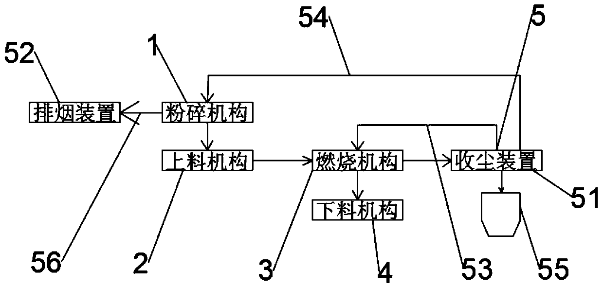
[0048] The high-temperature tail gas discharged after treatment by the tail gas treatment unit 5 contains relatively large heat energy, and this part of heat energy is often collected for industrial and domestic water use. In fact, this part of energy can also be used in the production process of desulfurization gypsum calcination to improve desulfurization Calcination process and product quality of gypsum calcination. specific:

[0049]Firstly: the high-temperature tail gas discharged by the tail gas treatment mechanism 5 is used for drying treatment when the crushing mechanism 1 crushes desulfurized gypsum. The original desulfurized gypsum generally contains a lot of water in the early stage of pulverization, and it is prone to sticking during the stirring process, and the desulfurized gypsum after pulverization may have uneven particles. If the drying degree of desulfurized gypsum is increased during the crushing process, the crushing efficiency of desulfurized gypsum will...

Embodiment 2

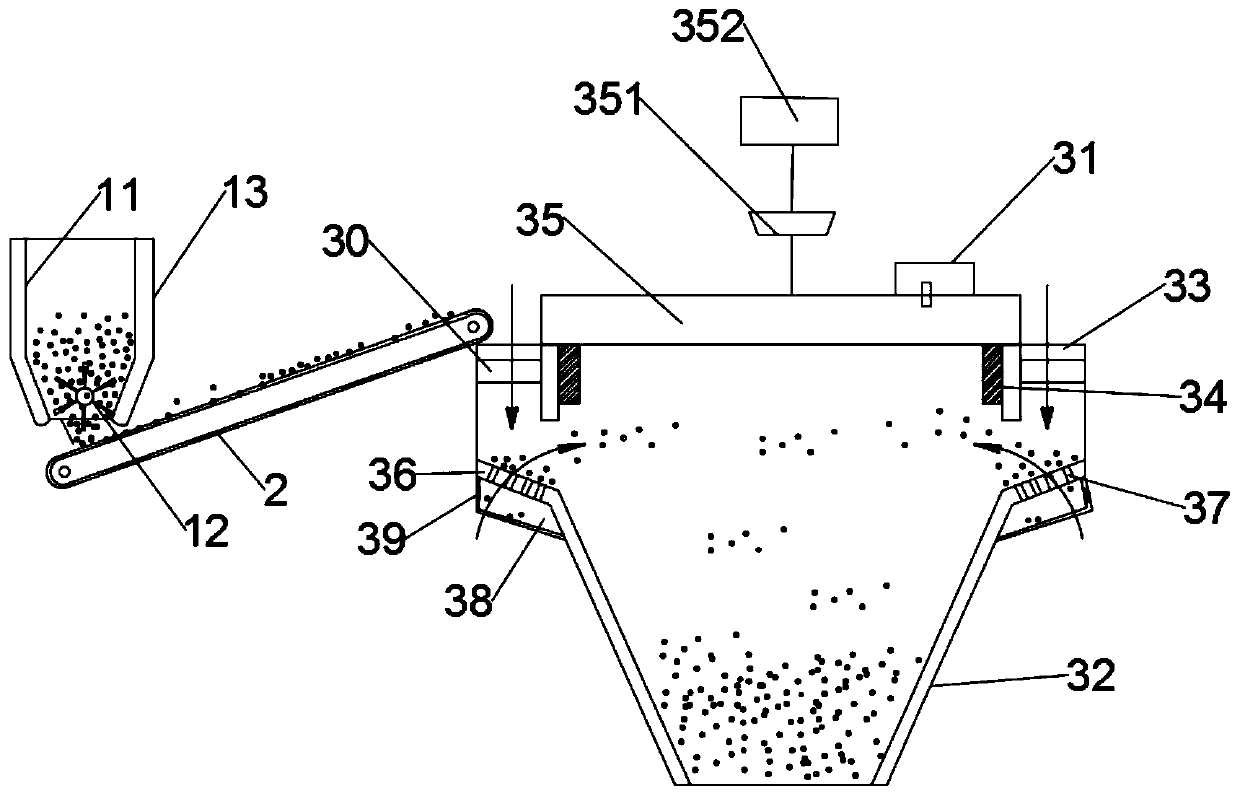
[0056] The combustion mechanism 3 utilizes the high-temperature exhaust gas through the first waste heat utilization pipe 53 . specific:

[0057] The combustion mechanism 3 includes a conical roller 32 driven to rotate by a power mechanism 31 , and a feeding ring 33 is provided on the periphery of the conical roller 32 . Preferably, a one-way passage valve plate 30 is provided above the feeding ring 33 for the entry of the materials but not for the internal dust to flow out. The one-way passage valve plate 30 is similar to the structure of the windshield of the smoke exhaust pipe of the range hood at the air outlet of the outer wall. It is mainly used to prevent the feed ring 33 from being blown out of the conical roller 32 under the action of the heat flow inside the conical roller 32 .

[0058] The central position of the inner ring of the feeding ring 33 is equipped with a stationary heating device 35 through a rotating bearing 34 , and the feeding end of the feeding mech...

Embodiment 3

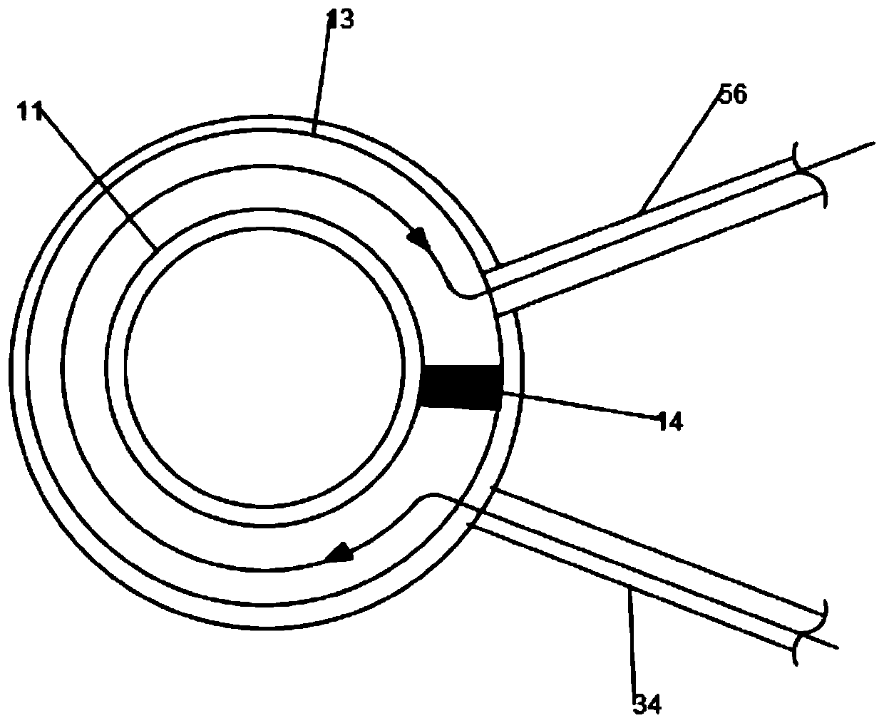
[0066] The crushing mechanism 1 includes a crushing tube 11 , and a rotary crushing device 12 is arranged inside the crushing tube 11 , and the rotary crushing device 12 can crush the dust inside the crushing tube 11 .

[0067] The outside of the crushing cylinder 11 is provided with a heat exchange hood 13 surrounding the wall of the crushing cylinder 11 . The tube wall of the heat exchange gas hood 13 and the tube wall of the pulverizing tube 11 encloses the syngas flow chamber. The second waste heat utilization pipe 54 passes the high-temperature exhaust gas into the air flow chamber, and conducts heat conduction with the wall of the crushing cylinder 11, and transfers the heat of the high-temperature exhaust gas to the desulfurized gypsum being crushed in the crushing cylinder 11, so that the gypsum is crushed evenly and the gypsum is improved. crushing efficiency. specific:

[0068] The heat exchange hood 13 is separated by the windshield 14, the heat exchange hood 13 o...


PUM


Abstract

Embodiments of the invention disclose a desulfurized-gypsum calcining device using natural gas as a heat source. The desulfurized-gypsum calcining device comprises a crushing mechanism, a feeding mechanism, a combustion mechanism, a discharging mechanism and a tail gas treatment mechanism. According to the invention, high-temperature tail gas discharged by the tail gas treatment mechanism is usedfor drying treatment of desulfurized gypsum during crushing of the desulfurized gypsum with the crushing mechanism; and high-temperature tail gas exhausted by the tail gas treatment mechanism can alsobe introduced into the combustion mechanism for air-drying of the desulfurized gypsum entering an inlet of the combustion mechanism, and the desulfurized gypsum is raised in the combustion mechanismby virtue of the high-temperature tail gas so as to increase the heating area of the desulfurized gypsum. A desulfurized-gypsum calcining method comprises the following steps: S100, crushing of the gypsum; S200, feeding; S300, combustion of the gypsum; S400, tail gas treatment; and S500, discharging. The high-temperature tail gas generated in the calcining process is used for crushing and combustion links in the process of calcining, so the utilization rate of heat energy in the gypsum calcining process is increased, and calcining efficiency is improved.

Description

technical field [0001] The embodiments of the present invention relate to the technical field of gypsum production, in particular to a desulfurized gypsum calcining device and a calcining method using natural gas as a heat source. Background technique [0002] The production of building gypsum adopts dry calcined gypsum process. In foreign countries, before the 1960s, traditional slow-fired intermittent woks and external-fired rotary kilns were the mainstays. In the late 1960s, the above equipment was technologically transformed. In the 1970s, intermittent woks were developed It became a continuous frying pan, and developed into a conical frying pan after the 1980s; the rotary kiln also developed from the external firing type to the internal firing type calcination; in order to promote the technological progress of the gypsum industry and increase the operating speed of the gypsum building material production line, and The air-flow rapid calcination process was developed. ...

Claims


Application Information

Patent Timeline
IPC IPC(8): C04B11/26C04B11/036F27D17/00F26B21/00B01D46/00
CPCB01D46/00C04B11/022C04B11/036C04B11/268F26B21/00F27D17/004F27D17/008Y02P10/143
Inventor 姚运家鞠宏胜李伯洋
Owner BEIJING NEW BUILDING MATERIALS PLC
Why Eureka
Try Eureka