Electrolytic corrosion resistance method for M-Bus wet-type photoelectric direct-reading water meter

A technology of photoelectric direct reading and electrolytic corrosion, which is applied in the direction of measuring devices, instruments, liquid/fluid solid measurement, etc., and can solve problems such as meter failure, shrinkage, and deepening of electrolytic corrosion of M-Bus wet photoelectric direct reading water meters, etc. , to achieve the effects of long power-on time, large resistance between conductors, and insensitive power-on time

Inactive Publication Date: 2019-12-17
HUNAN WEIMING ENERGY TECH CO LTD
View PDF9 Cites 1 Cited by
  • Summary
  • Abstract
  • Description
  • Claims
  • Application Information

AI Technical Summary

Problems solved by technology

[0005] In the prior art, the resistance between conductors on the circuit board in the M-Bus wet-type photoelectric direct reading water meter is greatly affected by water pressure and sealing conditions, and the resistance will gradually decrease with the normal operation time; When the bus is connected, the voltage between the conductors can be up to 36 volts; the power-on time varies due to the number of meters on the bus and the number of communications per day. Generally, it is 10-20 minutes per day (as long as the bus is powered on, the meters in the meter The circuit will be charged), in extreme cases it may be continuous power
[0006] In this case, the degree of electrolytic corrosion of the M-Bus wet-type photoelectric direct-reading water meter will continue to deepen, and some meters will fail before reaching the designed service life

Method used


Image

  • Electrolytic corrosion resistance method for M-Bus wet-type photoelectric direct-reading water meter
  • Electrolytic corrosion resistance method for M-Bus wet-type photoelectric direct-reading water meter
  • Electrolytic corrosion resistance method for M-Bus wet-type photoelectric direct-reading water meter

Examples


Embodiment 1

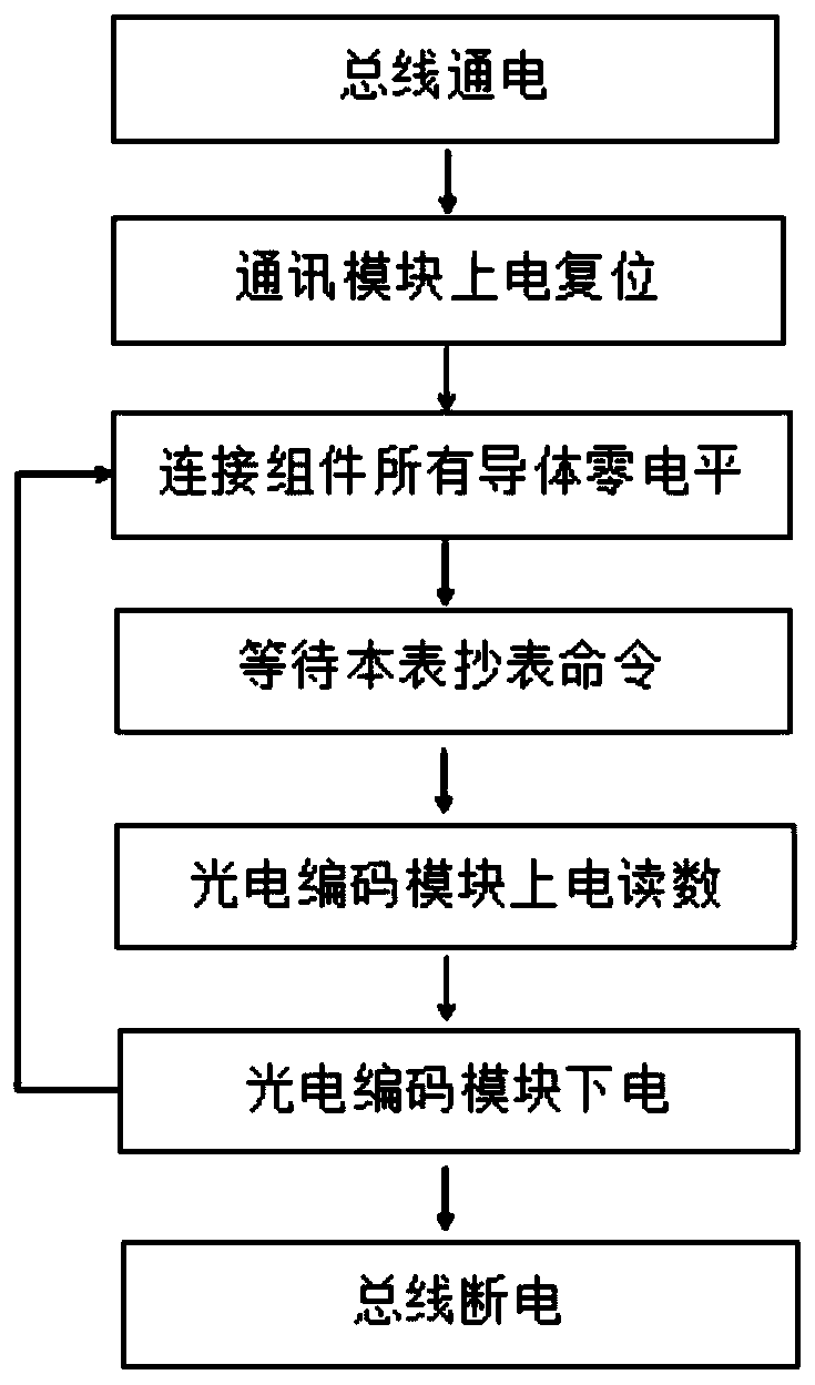
[0036] Example 1, such as figure 1 As shown, the embodiment of the present invention provides an M-Bus wet-type photoelectric direct-reading water meter anti-electrolytic corrosion method, comprising the following steps:

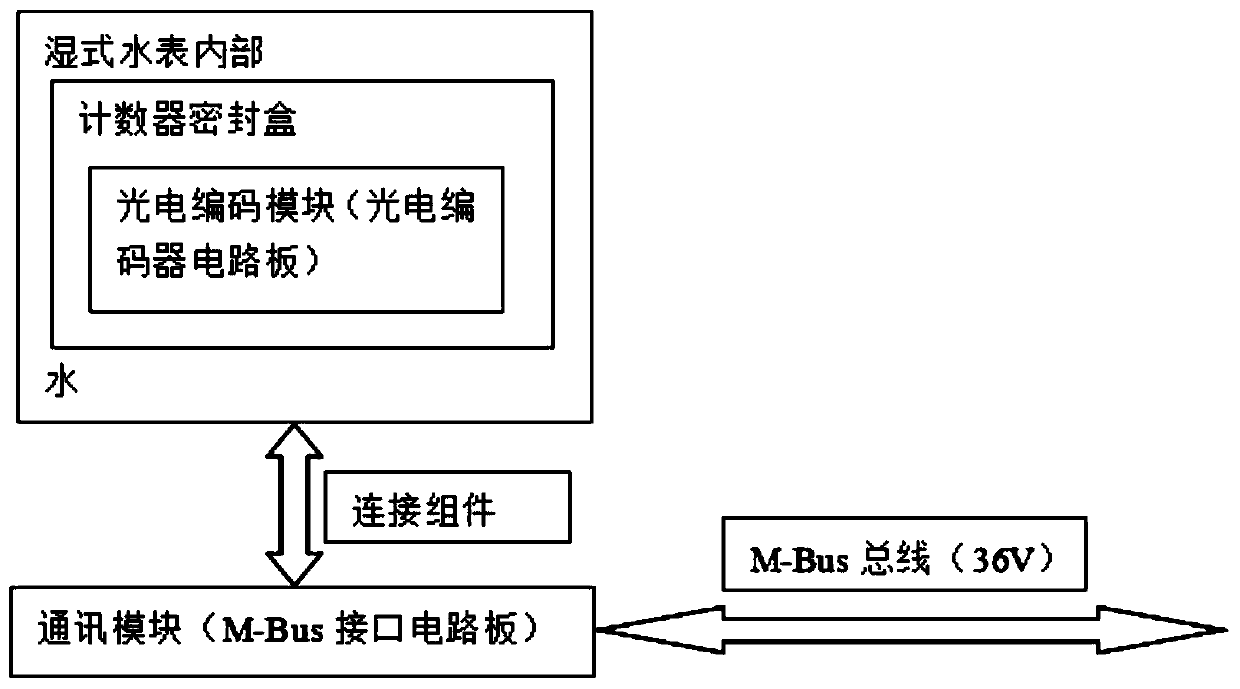
[0037] Step 1. Divide the internal circuit of the water meter counter into two parts: a communication module and a photoelectric coding module. The photoelectric coding module is located on the counter inside the water meter. The communication module is moved out of the water meter and is located outside the water meter with a relatively good environment. The communication module and The M-Bus bus is connected, and the communication module and the photoelectric encoding module are connected through a connecting component;

[0038] Step 2. Power on the M-Bus bus, power on and reset the communication module to start working, and do not power on the photoelectric encoding module, and all the electrical connection conductors in the connection components are at z...


PUM


Abstract

The invention discloses an electrolytic corrosion resistance method for an M-Bus wet-type photoelectric direct-reading water meter. The method comprises the following steps that 1, a circuit in a water meter counter is divided into a communication module and a photoelectric coding module, the photoelectric coding module is located on the counter inside the water meter, the communication module ismoved out of the water meter and located outside the water meter with a relatively good environment, the communication module is connected with the M-Bus, and the communication module is connected with the photoelectric coding module through a connecting assembly; 2, the M-Bus is powered on, the communication module is powered on and reset to start working, the photoelectric coding module is not powered on, and all electric connection conductors in the connection assembly are located at a zero level potential; 3, when the M-Bus commands to read the meter, the photoelectric coding module is powered on and carries out reading once, and then the photoelectric coding module is powered off; and 4, the M-Bus is powered off. Compared with a common M-Bus wet-type photoelectric direct-reading watermeter, the M-Bus wet-type photoelectric direct-reading water meter is insensitive to the power supply time of the M-Bus, and the failure rate caused by electrolytic corrosion is low.

Description

technical field [0001] The invention relates to an M-Bus wet-type photoelectric direct-reading water meter, in particular to a method for resisting electrolytic corrosion of an M-Bus wet-type photoelectric direct-reading water meter. Background technique [0002] M-Bus wet-type photoelectric direct-reading water meter is a kind of wired remote water meter with a photoelectric absolute position encoder installed on the mechanical counter of the wet-type water meter and reads the meter through the M-Bus bus. [0003] Usually, the photoelectric absolute position encoding circuit and the M-Bus bus interface circuit of the M-Bus wet photoelectric direct reading water meter are installed in the mechanical counter of the wet water meter, which is continuously affected by the change of water pressure. Under the influence of various factors (pressure change, temperature change, sealing material aging, continuous charging), electrolytic corrosion will occur between conductors (solder ...

Claims


Application Information

Patent Timeline
Patent Type & Authority Applications(China)
IPC IPC(8): G01F15/06
CPCG01F15/065G01F15/068
Inventor 罗军
Owner HUNAN WEIMING ENERGY TECH CO LTD
Why Eureka
Try Eureka