An oilfield wastewater treatment device

A wastewater treatment and oilfield technology, which is applied in mining wastewater treatment, water/sewage treatment, water/sludge/sewage treatment, etc., can solve problems affecting mass transfer efficiency, affecting water-soluble gas rate, low mechanical strength, etc., to improve The effect of mass transfer efficiency, improvement of mechanical strength, and improvement of mass transfer rate

Active Publication Date: 2022-04-22
大庆市普罗石油科技有限公司
View PDF4 Cites 0 Cited by
  • Summary
  • Abstract
  • Description
  • Claims
  • Application Information

AI Technical Summary

Problems solved by technology

[0003] 1. The filler of the existing pressure dissolved air tank generally adopts the step ring, but the installation process of the step ring filler is to pour it into the tank, and then arrange it on the cross section, and repeat the operation several times to fill the height of the filler It is enough to reach the required height. Although the stepped ring packing is provided with flanging, it is difficult to ensure that the stepped ring packing is in the correct direction. Once the direction of the bottom is reversed, it will be more difficult to level the packing. , the operation is inconvenient and time-consuming, and the compactness of the packing in this filling method will be relatively low, resulting in low mechanical strength, and the loose packing will affect the pressure drop and efficiency of the packing layer, thus affecting water solubility
[0004] 2. The waste water from the existing pressure dissolved air tank has a tendency to gradually concentrate towards the tank wall when the packing layer flows downward. Since the packing layer is in direct contact with the pipe wall, the distance between the edge of the packing layer and the tank wall is small, and it is impossible to solve the liquid In the problem of flowing from the edge of the packing layer to the tank wall, the liquid flow near the tank wall gradually increases, resulting in the phenomenon of "wall flow", which will cause the gas-liquid two-phase distribution in the packing layer to be uneven, which will cause Further affect the mass transfer efficiency

Method used


Image

  • An oilfield wastewater treatment device
  • An oilfield wastewater treatment device
  • An oilfield wastewater treatment device

Examples


Embodiment Construction

[0018] The following will clearly and completely describe the technical solutions in the embodiments of the present invention with reference to the accompanying drawings in the embodiments of the present invention. Obviously, the described embodiments are only some, not all, embodiments of the present invention. Based on the embodiments of the present invention, all other embodiments obtained by persons of ordinary skill in the art without making creative efforts belong to the protection scope of the present invention.

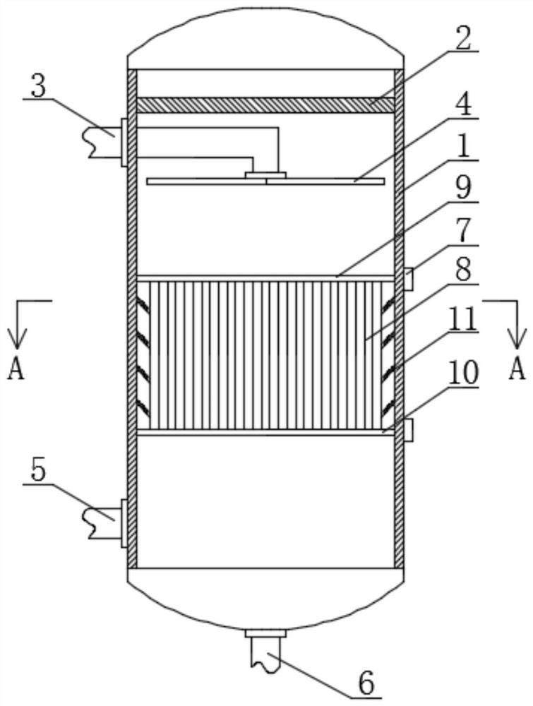
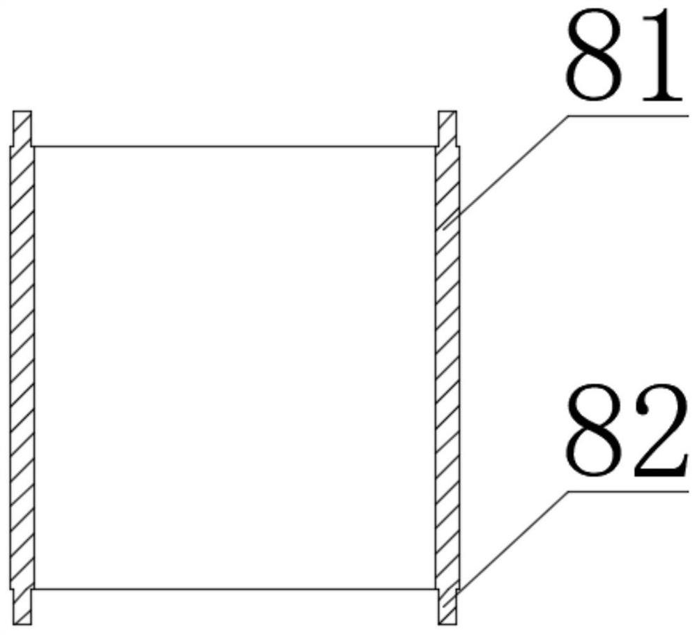
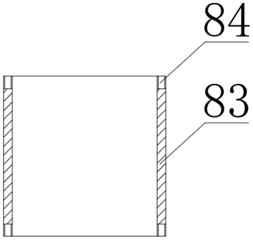
[0019] see Figure 1-4 , a kind of wastewater treatment device for oil fields, comprising a tank wall 1, a demister 2 is fixedly installed on the upper part of the inner wall of the tank wall 1, and a water inlet 3 is fixedly installed on one side of the outer wall of the tank wall 1, and the water inlet 3 is fixedly installed through a connecting pipe There is a water distributor 4, an air inlet 5 is fixedly installed at the bottom of one side of the tank wal...


PUM


Abstract

The invention relates to the technical field of wastewater treatment, and discloses a wastewater treatment device for oilfields, comprising a tank wall, a demister is fixedly installed on the upper part of the inner wall of the tank wall, and a water inlet is fixedly installed on one side of the outer wall of the tank wall , the waste water treatment device for oil fields, by setting the packing to a triangular shape in cross-section, and adding a packing frame to the tank, the first packing and the second packing are installed alternately in advance through the clamping block and the clamping groove, and then the packing is put in In the frame, and because the first packing and the second packing are triangular, they will be fitted with hypotenuses between the adjacent first packing and the second packing in each layer, which ensures the stability of each layer of packing, and does not It will move due to the internal force to avoid affecting the dissolved gas rate, and the clamping and fixing structure of the clamping block and the clamping groove has greatly improved the compactness of the entire packing layer, thereby improving the waste water and gas in it. mass transfer rate.

Description

technical field [0001] The invention relates to the technical field of wastewater treatment, in particular to a wastewater treatment device for oil fields. Background technique [0002] There are a lot of equipment in the wastewater treatment device in the oil field, among which the pressure dissolved air tank plays an important role in the wastewater treatment process. It is a kind of airtight pressure vessel. Its working principle is to pressurize the wastewater to a specified pressure. The water inlet is sent to the water distributor, and the water distributor is used to evenly sprinkle the waste water on the filler below, and then the compressed air is sent from the air inlet to the dissolved air tank, and the air is more dissolved in the water under high pressure conditions. , and then discharge the water through the water outlet at the bottom, but there are always some problems in the existing pressure dissolved air tank: [0003] 1. The filler of the existing pressur...

Claims


Application Information

Patent Timeline
Patent Type & Authority Patents(China)
IPC IPC(8): C02F1/00C02F103/10
CPCC02F1/006C02F1/00C02F2103/10
Inventor 郭英健丛日东杨凤凯姚炳龙孙庆伟周敏杰于国江李晶张化庆
Owner 大庆市普罗石油科技有限公司
Why Eureka
Try Eureka