Fluid flow intelligent control solar energy system

A technology of solar energy and flow, which is applied in the field of heat collecting tubes, can solve the problems of low intelligence, high temperature, and low heat exchange efficiency, and achieve the effects of increasing heat transfer speed, avoiding uneven heating, and satisfying absorption capacity

Active Publication Date: 2019-12-24
SHENZHEN SWALLE TECH CO LTD
View PDF8 Cites 3 Cited by
  • Summary
  • Abstract
  • Description
  • Claims
  • Application Information

AI Technical Summary

Problems solved by technology

Current heat collecting tubes are also widely used in the treatment of various diseases, especially in the treatment of chronic diseases caused by aging and old damage to muscles and ligaments, such as CN2167709Y patent, but in the current prior art, such as CN2167709Y patent , because the steam generated directly by heating will cause the temperature of the generated steam to be too high, and it will cause too much moisture in the generated steam, and the drug may be deposited in the lower part because it is a particle, so the active ingredient in the ejected steam The content is too low, and the temperature is too high, and the degree of intelligence in the existing technology is not high, and effective intelligent operation cannot be carried out
[0005] In the background technology, when using solar energy to heat the heat collecting tube, the solar energy either directly heats the heat collecting tube, or generates steam through secondary heat exchange, especially directly heats the heat collecting tube, and uses the convective heat exchange inside the heat collecting tube to carry out the heating of the upper and lower parts of the heat collecting tube. Fluid convection heat exchange, but in this case, the hot fluid in the lower part needs to be naturally convected to the upper part, and the heat transfer efficiency is low

Method used


Image

  • Fluid flow intelligent control solar energy system
  • Fluid flow intelligent control solar energy system
  • Fluid flow intelligent control solar energy system

Examples


Embodiment Construction

[0033] The specific embodiments of the present invention will be described in detail below in conjunction with the accompanying drawings.

[0034] In this article, if there is no special explanation, when involving formulas, " / " means division, and "×" and "*" mean multiplication.

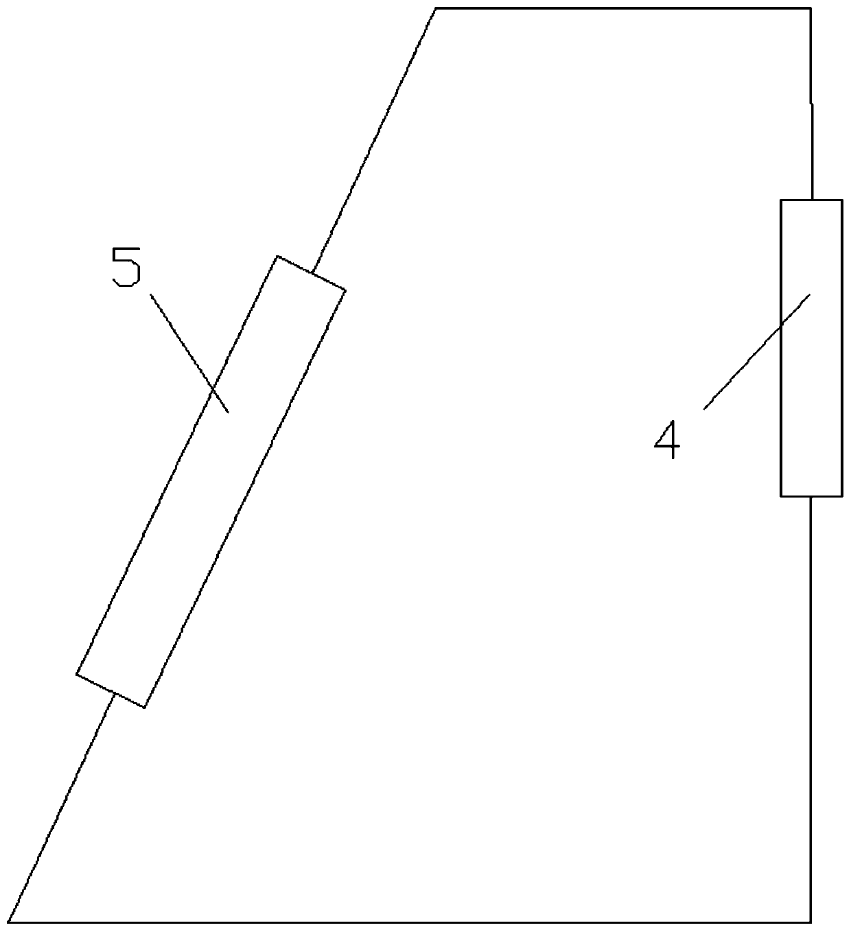
[0035] figure 1 A solar energy system is disclosed, the solar energy system includes a solar heat collector 5 and a heat utilization device 4, the solar heat collector absorbs solar energy, heats a fluid flowing through it, and then the fluid enters the heat utilization device for utilization.

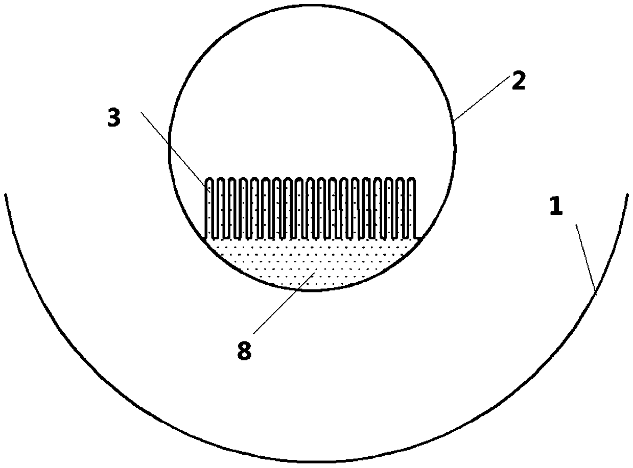
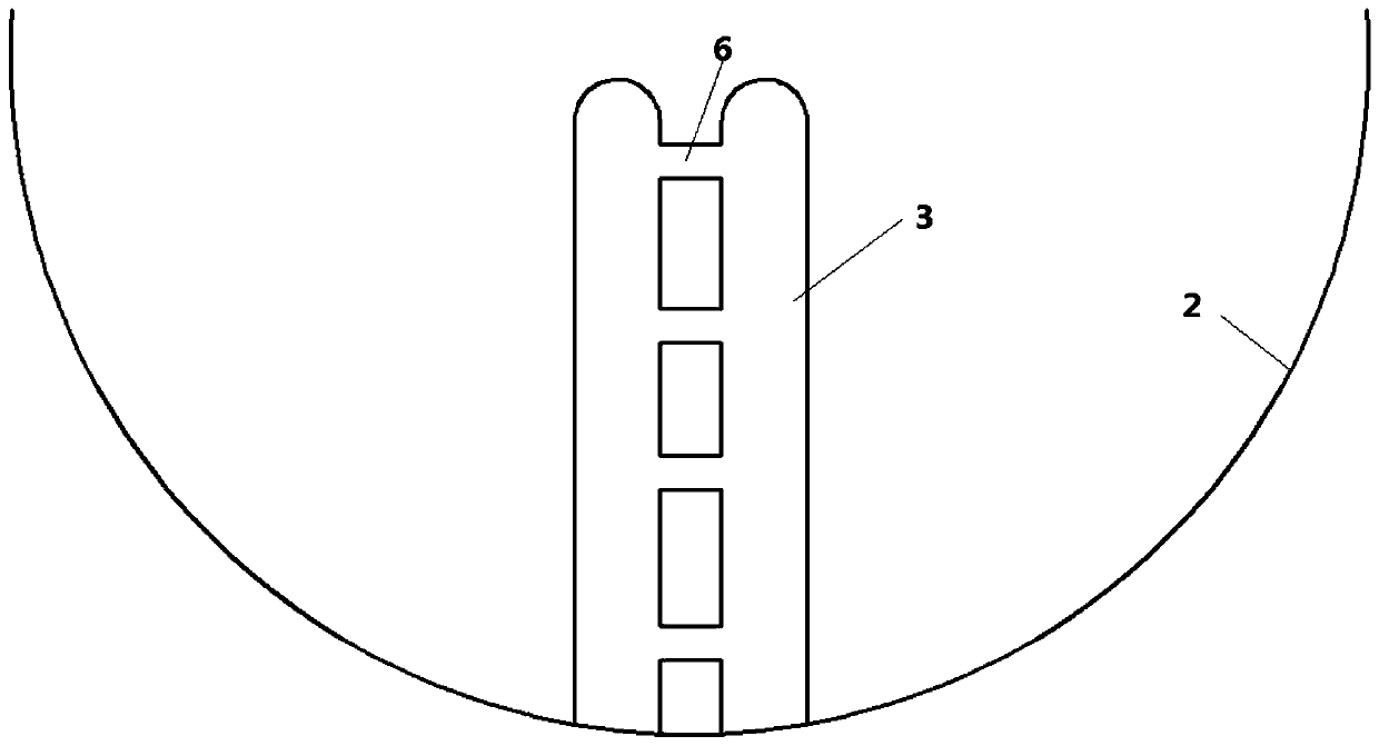
[0036] Such as Figure 2-5 Disclosed is a trough solar heat collector 5 using heat pipes, the heat collector includes a reflector 1 and a heat collection tube 2, the heat collector 2 is located at the focal point of the reflector 1, and the reflector 1 reflects solar energy The heat collecting tube 2 is used to heat the water in the heat collecting tube 2, and the heat collector also includes heat pipes ...


PUM


Abstract

The invention provides a solar energy system. The solar energy system comprises a reflecting mirror and heat collection tubes. A central control unit is in data connection with a valve 16, a valve 14,a valve 15 and a temperature sensor so as to monitor the opening degrees of the valve 16, the valve 14 and the valve 15 and the temperature measured by the temperature sensor. When the temperature measured by the temperature sensor is lower than a certain temperature, the central control unit controls the opening degree of the valve 14 to be increased and the opening degree of the valve 15 to bereduced so as to increase the flow of hot water getting into a heat radiator and increase the heat dissipation capacity. When the temperature measured by the temperature sensor is higher than a certain temperature, the central control unit controls the opening degree of the valve 14 to be reduced and the opening degree of the valve 15 to be increased so as to reduce the flow of hot water getting into the heat radiator and reduce the heat dissipation capacity. In this control mode, the solar energy system can reasonably utilize heat of a heat accumulator to prevent heat loss.

Description

technical field [0001] The invention relates to a heat collecting tube technology, in particular to a heat collecting tube of a heat pipe with a new structure. Background technique [0002] Heat pipe technology was developed in Los Alamos, USA in 1963. national laboratory A heat transfer method called a "heat pipe" invented by George Grover element , it makes full use of the principle of heat conduction and the rapid heat transfer properties of phase change media, and quickly transfers the heat of the heating object to the heat source through the heat pipe, and its thermal conductivity exceeds that of any known metal. [0003] Heat pipe technology was widely used in aerospace, military and other industries before. Since it was introduced into the radiator manufacturing industry, people have changed the traditional radiator design ideas and got rid of the single heat dissipation mode that only relies on high air volume motors to obtain better heat dissipation. The use of h...

Claims


Application Information

Patent Timeline
Patent Type & Authority Applications(China)
IPC IPC(8): F22B1/00F24S23/70F24S10/70F24S10/95F24S80/00
CPCF22B1/006Y02E10/44
Inventor 不公告发明人
Owner SHENZHEN SWALLE TECH CO LTD
Why Eureka
Try Eureka