Heap thermal desorption treatment system for repairing organic contaminated soil

A technology of organic pollution and treatment system, applied in the field of contaminated site remediation, can solve the problems of unsuitable pollution distribution and scattered contaminated soil remediation, low heating temperature of contaminated soil, etc., and achieves the effects of easy operation, simple composition and low operating cost.

Pending Publication Date: 2019-12-27
ZHONGKE DINGSHI ENVIRONMENTAL ENG CO LTD
View PDF1 Cites 7 Cited by
  • Summary
  • Abstract
  • Description
  • Claims
  • Application Information

AI Technical Summary

Problems solved by technology

[0006] The purpose of the present invention is to solve the problem that the existing in-situ thermal desorption is not suitable for remediation of polluted soil with scattered pollution distribution and shallow pollution depth, and to provide a heap thermal desorption treatment system for remediating organic polluted soil. The indirect thermal desorption technology of batch treatment can excavate scattered and especially shallow polluted soil and collect it into a well-built treatment system, and then heat the polluted soil to achieve the purpose of removing volatile and semi-volatile pollutants. Compared with the ectopic thermal desorption repair mode of the rotary kiln, the heating temperature of the contaminated soil is lower, the amount of repaired soil can be large or small, and the collection and treatment of exhaust gas are more controllable; Keep the ground pollution isolation layer and the surrounding external insulation layer, and only remove the polluted soil, top insulation layer, internal heating pipe, extraction pipe, monitoring pipe, etc., to realize the reuse of the thermal desorption treatment system of the pile

Method used


Image

  • Heap thermal desorption treatment system for repairing organic contaminated soil
  • Heap thermal desorption treatment system for repairing organic contaminated soil
  • Heap thermal desorption treatment system for repairing organic contaminated soil

Examples


Embodiment Construction

[0030] Some specific embodiments of the present invention will be described in detail below in an exemplary and non-limiting manner with reference to the accompanying drawings. The same reference numerals in the drawings designate the same or similar parts or parts. It should be understood by those skilled in the art that these drawings are not necessarily drawn to scale.

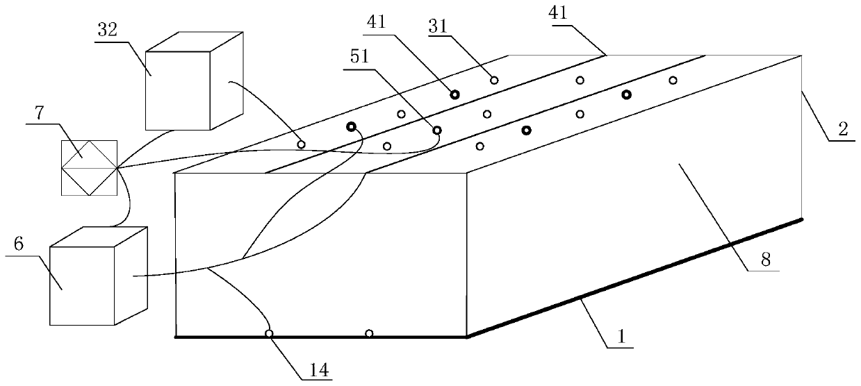
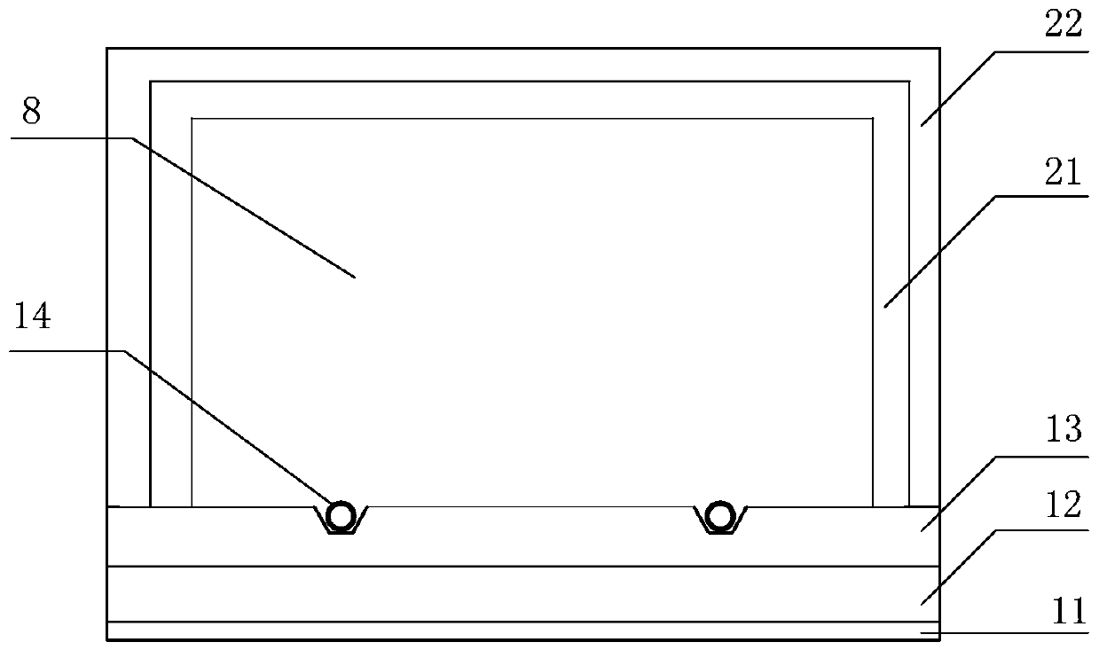
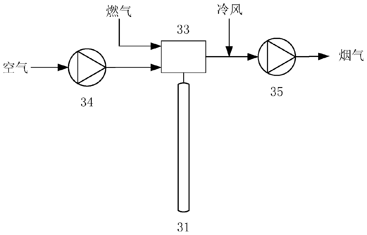
[0031] like figure 1 , figure 2 , image 3 , Figure 4 , Figure 5 As shown, the present invention provides a kind of thermal desorption treatment system of organic polluted soil heap, comprising:

[0032] The ground pollution isolation layer 1 consists of HDPE membrane 11, gravel layer 12, concrete layer 13 and leachate collection pipe 14 from bottom to top. HDPE membrane 11 is first laid on the bottom, and gravel and concrete are laid in sequence on the top as the isolation layer. A leachate collection pipe 14 is provided, and the end of the leachate collection pipe is connected to the tail water t...


PUM


Abstract

The invention provides a heap thermal desorption treatment system for repairing organic contaminated soil. The system comprises: a closed space defined by a ground sewage isolation layer and an external heat preservation layer; a heating system which comprises a plurality of heating pipes vertically arranged in the closed space; an extraction system that comprises extraction pipes which are horizontally and vertically arranged in the closed space; and a tail gas treatment system which is arranged outside the closed space and comprises a gas-liquid separation unit, tail gas treatment units andtail water treatment units, which are arranged on different downstream branches of the gas-liquid separation unit; the extraction pipe is connected with the upstream of the gas-liquid separation unit;and a percolate collecting pipeline arranged on the ground sewage isolation layer is connected with the tail water treatment unit. According to the method, dispersedly distributed soil, especially shallow polluted soil, is excavated and then piled, so that the purpose of removing volatile and semi-volatile pollutants is achieved by heating the polluted soil. The method is simple in composition, easy to operate, high in energy efficiency, low in operation cost, free of long-distance transportation, safe and risk-free in the treatment process and capable of achieving multiple times of remediation and utilization.

Description

technical field [0001] The invention relates to the technical field of remediation of contaminated sites, in particular to a thermal desorption treatment system for piles of organic polluted soil. Background technique [0002] The industrial production process causes the soil to be polluted to varying degrees, causing serious harm to the ecological environment and human health, and restricting the development and utilization of land. There are different degrees of organic pollution in various plots involving the chemical industry, mining industry, metallurgy industry and other industries in our country. Among them, for the soil with volatile and semi-volatile pollutants, in-situ thermal desorption repair technology is a very effective treatment method . [0003] The in-situ thermal desorption technology directly heats the polluted soil to the target temperature, and by controlling the soil temperature and holding time, the pollutants are gasified and volatilized, and the ta...

Claims


Application Information

Patent Timeline
Patent Type & Authority Applications(China)
IPC IPC(8): B09C1/06
CPCB09C1/06B09C1/062
Inventor 刘晶晶陈恺刘爽王海东李万斌王晨晨杨勇
Owner ZHONGKE DINGSHI ENVIRONMENTAL ENG CO LTD
Why Eureka
Try Eureka