Post-treatment device and method for complex DMF wastewater subjected to DMF recovery

A post-processing device and wastewater recovery technology, which is applied in natural water treatment, heating water/sewage treatment, water/sludge/sewage treatment, etc., can solve the problems of inability to recycle resources and high energy consumption, and reduce the tower top Condenser, reduced process energy consumption, effect of reduced demand

Pending Publication Date: 2019-12-27
吴嘉
View PDF17 Cites 1 Cited by
  • Summary
  • Abstract
  • Description
  • Claims
  • Application Information

AI Technical Summary

Problems solved by technology

[0007] In view of this, the purpose of the present invention is to provide a post-processing device and method after complex DMF wastewater reclaims DMF, to solve the problem of incapable resource processing in the prior art when complex DMF wastewater reclaims DMF and further processes dimethylamine and other VOCs and deal with high energy consumption

Method used


Image

  • Post-treatment device and method for complex DMF wastewater subjected to DMF recovery
  • Post-treatment device and method for complex DMF wastewater subjected to DMF recovery

Examples


specific Embodiment 1

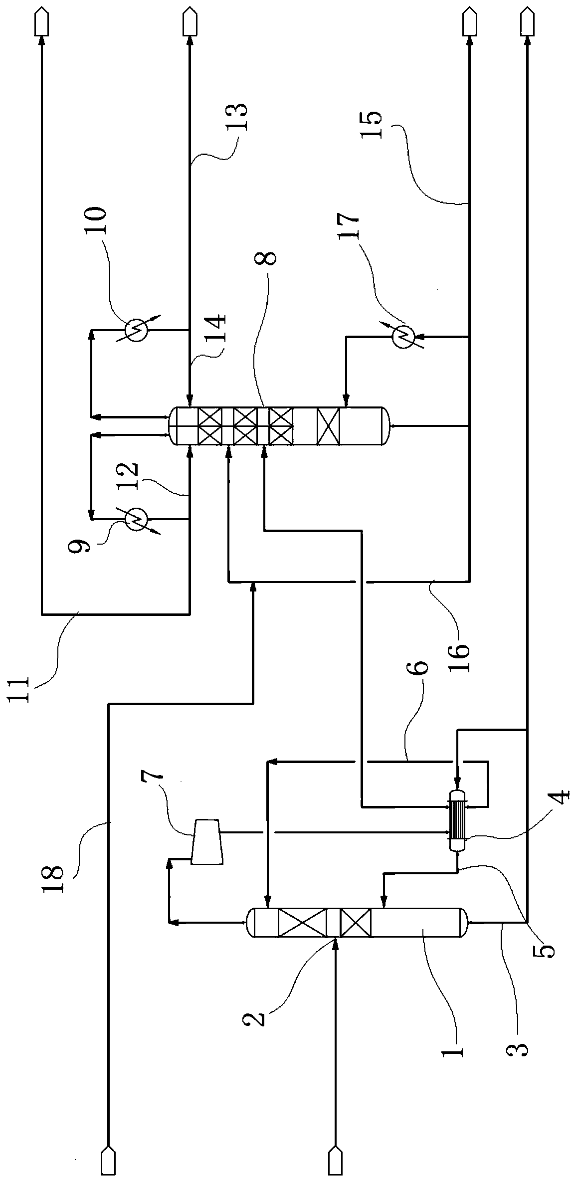
[0042] see figure 1 , a post-treatment device for reclaiming DMF from complex DMF wastewater, used to treat wastewater after reclaiming DMF, including a stripper unit that feeds waste water and a light component treatment unit that is connected to the stripper unit; the stripper unit includes Stripping tower 1, be arranged on the waste water inlet 2 that is communicated with waste water on the stripping tower 1 and be arranged on the stripping tower effluent pipeline 3 at the bottom of the stripping tower 1, be connected on the stripping tower effluent pipeline 3 Stripping tower reboiler 4, this stripping tower reboiler 4 communicates with stripping tower 1 and is provided with the first stripping tower reflux branch 5 and the second stripping tower reflux branch 6, the first stripping tower The reflux branch 5 and the second stripper reflux branch 6 respectively return to the stripper 1, and the top of the stripper 1 is also connected with a light component compressor 7, and ...

specific Embodiment 2

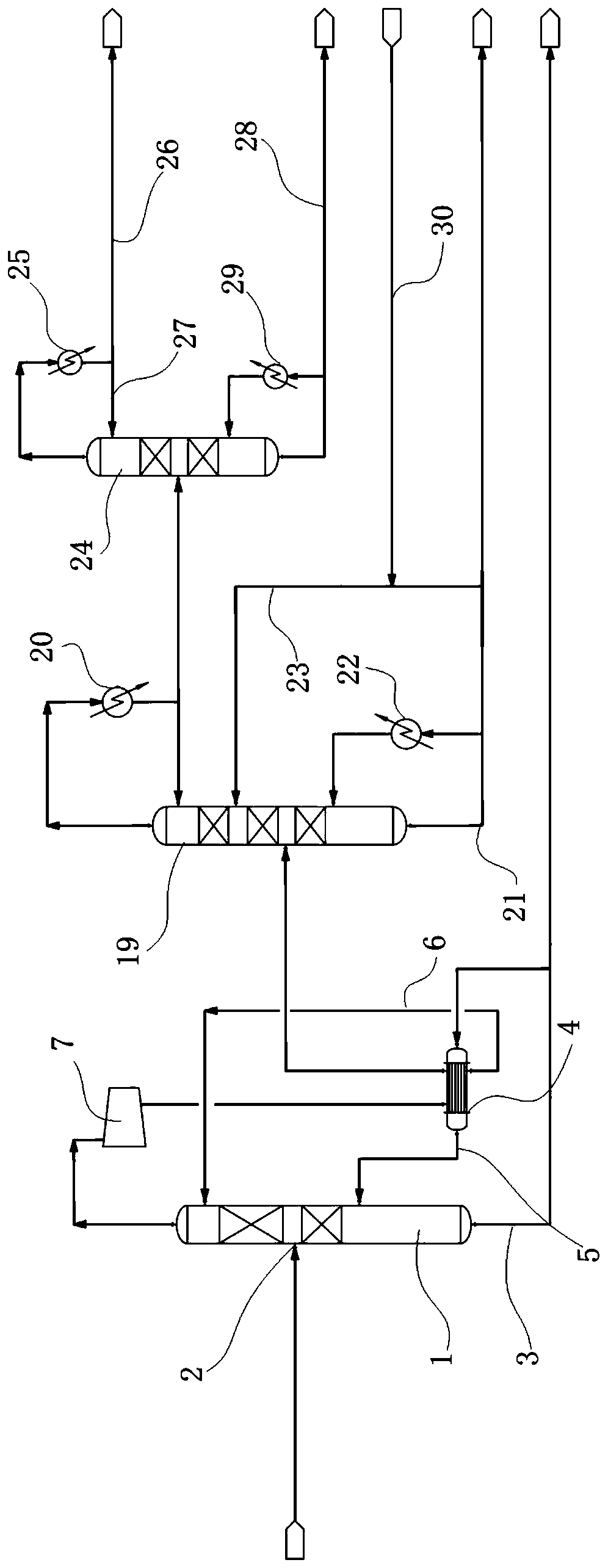
[0065] see figure 2, the difference from specific embodiment 1 is that its light component treatment unit is the light component refining tower 24 that is connected with the ammonia removal tower 19 and the ammonia removal tower 19; the top of the ammonia removal tower 19 is communicated with the ammonia removal tower condenser 20, the amine removal tower condenser 20 is respectively connected to the light component refining tower 24 and refluxed to the amine removal tower 19; The pipeline 21 is respectively communicated with a de-amine tower reboiler 22 and a de-amine tower reflux branch 23, the de-amine tower reboiler 22 is connected to the de-amine tower 19, and the de-amine tower reflux branch 23 is refluxed to the de-amine tower 19 The top of light component refining tower 24 is provided with light component refining tower condenser 25, and this light component refining tower condenser 25 is communicated with first light component refining tower effluent pipeline 26 and ...


PUM


Abstract

The invention belongs to the field of wastewater treatment. The invention relates to a post-treatment device and method forcomplex DMF wastewater subjected to DMF recovery. The method is used for treating wastewater after DMF recovery. A stripping tower unit and a light component treatment unit are arranged; dimethylamine and other VOCs are recycled respectively, resource utilization of all lightcomponents is achieved, dimethylamine is prepared into dimethylamine salt which is directly used as a product or used for preparing dimethylamine, other VOCs can be recycled to a tanning link to be used as an auxiliary agent and can also be used as a paint diluent, and resource waste is avoided; and meanwhile, energy-saving means such as heat pump rectification and a dividing wall rectification tower are used, so that the energy consumption of a post-treatment process is effectively reduced, the number of equipment and the occupied area are reduced, and good economy is achieved.

Description

technical field [0001] The invention belongs to the field of waste water treatment and relates to a post-processing device and method for recovering DMF from complex DMF waste water. Background technique [0002] Polyurethane (PU) synthetic leather is an important part of the plastics industry. It is widely used in various industries of the national economy, and its application fields pervade all aspects of people's daily life. The production of synthetic leather generally uses polyurethane as the basic raw material for the base layer and the surface layer, and is obtained by solution polymerization through N,N-dimethylamide (DMF) as the main solvent. The production process is divided into wet process and dry process. . A large amount of DMF wastewater is produced during the production of synthetic leather. In the wet process, DMF is mainly precipitated from the resin in the washing process and dissolved in water to form DMF wastewater; in the dry process, DMF is mainly vo...

Claims


Application Information

Patent Timeline
Patent Type & Authority Applications(China)
IPC IPC(8): C02F1/04C07C209/00C07C209/86C07C211/04C02F103/38
CPCC02F1/04C07C209/00C07C209/86C02F2103/38C07C211/04Y02P20/10
Inventor 张相端吴嘉鲍艳
Owner 吴嘉
Why Eureka
Try Eureka