
Driving device for DFB laser in quantum key distribution

A DFB laser and quantum key distribution technology, applied in key distribution, can solve the problems of unstable output power, complex circuit volume, etc., and achieve the effects of stable output power, stable luminous power ratio, and reduced volume

Active Publication Date: 2019-12-27
QUANTUMCTEK
View PDF7 Cites 5 Cited by
  • Summary
  • Abstract
  • Description
  • Claims
  • Application Information

AI Technical Summary

Problems solved by technology

[0010] The technical problem to be solved by the present invention is how to solve problems such as complex circuits, large volume caused by many devices, and unstable output power caused by DFB lasers using voltage drive signals

Method used


Image

  • Driving device for DFB laser in quantum key distribution
  • Driving device for DFB laser in quantum key distribution
  • Driving device for DFB laser in quantum key distribution

Examples


Embodiment 1

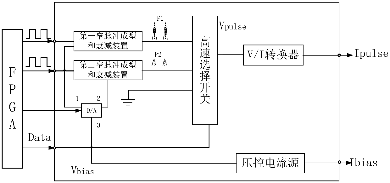
[0050] Such as figure 2 As shown, the driving device for the DFB laser in the quantum key distribution of the first embodiment of the present invention includes FPGA (Field-Programmable Gate Array, field programmable gate array), the first narrow pulse shaping and attenuation device, the second narrow pulse Pulse shaping and attenuation devices, high-speed selector switches, D / A (digital / analog) converters, V / I (voltage / current) converters, voltage-controlled current sources.

[0051] The FPGA output terminal is respectively connected to the input terminal of the first narrow pulse shaping and attenuating device, the input terminal of the second narrow pulse shaping and attenuating device, the input terminal of the D / A converter and the control terminal of the high-speed selection switch. The output end of the first narrow pulse shaping and attenuating device, the output end of the second narrow pulse shaping and attenuating device are respectively connected to the first sele...

Embodiment 2

[0068] Such as Figure 10 As shown, the driving device for the DFB laser in the quantum key distribution of the second embodiment of the present invention includes an FPGA (Field-Programmable Gate Array, i.e. Field Programmable Gate Array), a first narrow pulse shaping device, a second narrow pulse shaping device, a first V / I (voltage / current) converter, a second V / I (voltage / current) converter, a D / A (digital / analog) converter, a first bias current adjustment circuit, a second bias Set current regulation circuit, voltage-controlled current source.

[0069] The FPGA output terminal is respectively connected to the input terminal of the first narrow pulse shaping device, the input terminal of the second narrow pulse shaping device, and the input terminal of the D / A converter. The output end of the first narrow pulse shaping device is connected to the first V / I converter, the output end of the second narrow pulse shaping device is connected to the second V / I converter, the firs...


PUM


Abstract

The invention discloses a driving device for a DFB laser in quantum key distribution. The driving device comprises a controller, two narrow pulse forming devices and a signal adjusting device, the narrow pulse forming devices and the signal adjusting device are integrated on one chip; the controller is connected to the two narrow pulse forming devices and the signal adjusting device, the signal adjusting device adjusts signals output by the two narrow pulse forming devices respectively, and the controller outputs two paths of homologous clock signals to the two narrow pulse forming devices respectively and outputs one path of control signals to the signal adjusting device. Compared with the prior art, the driving devicehas the following advantages that the modules are integrated, chippedand miniaturized, the size of the modules achieving the same function is greatly reduced, and the size and the weight of the whole vehicle body are reduced; a controller is used for directly controlling generation of a homologous clock and preparing narrow pulses representing a decoy state and a signal state, and the narrow pulses can rise or fall in a self-adaptive mode according to modulation performance.

Description

technical field [0001] The invention relates to the technical field of quantum key distribution, and more specifically relates to a device for driving a DFB laser in a quantum key distribution (QKD) system. Background technique [0002] In today's society, with the development of science and technology, human beings have entered the information society. And people have more and more needs for information security, to protect the information security of the country as small as everyone. In order to solve the potential security problems of information, quantum cryptography came into being. Quantum cryptography is an encryption and decryption scheme designed using the quantum properties of matter, and its security is based on the basic principles of quantum mechanics. The currently widely used protocol is the QKD scheme proposed by Bennett and Brassard in 1984, which is called the BB84 protocol. The unconditional security of the BB84 protocol using ideal devices has been str...

Claims


Application Information

Patent Timeline
Patent Type & Authority Applications(China)
IPC IPC(8): H04B10/50H04B10/524H04B10/54H04B10/70H04L9/08H01S5/042
CPCH04B10/503H04B10/524H04B10/541H04B10/70H04L9/0852H01S5/042
Inventor 代云启马睿罗登朱珠
Owner QUANTUMCTEK
Learn More