
Device for purifying treatment of chemical exhaust gas

A waste gas purification and treatment device technology, which is applied in the direction of gas treatment, air quality improvement, chemical instruments and methods, etc., can solve the problems of affecting the absorption effect of biofilm, affecting the normal operation of the device, and the effect of waste gas pre-wetting is not good, so as to achieve the guarantee Effects of service life, increased pressure, and increased humidity

Active Publication Date: 2020-01-03
上海安居乐环保科技股份有限公司
View PDF6 Cites 0 Cited by
  • Summary
  • Abstract
  • Description
  • Claims
  • Application Information

AI Technical Summary

Problems solved by technology

[0003] Chemical waste gas is usually purified by biofilm technology. Before the treatment, the waste gas needs to be pressurized and pre-wetted before being discharged into the filter tower, so that it can be absorbed by contact with the biofilm. The short stay time in the air makes the pre-wet effect of the exhaust gas not good, which affects the subsequent biofilm absorption effect
[0004] However, the larger particles contained in the chemical waste gas passing through the interior of the existing humidification tank fall to the bottom after encountering water mist, and accumulate more and more with the increase of time, thus affecting the normal operation of the device , and the interior of the humidification tank is difficult to disassemble and clean due to the setting of the partition and the circular plate, which further affects the use. Accordingly, the present invention proposes a chemical waste gas purification treatment device

Method used


Image

  • Device for purifying treatment of chemical exhaust gas
  • Device for purifying treatment of chemical exhaust gas
  • Device for purifying treatment of chemical exhaust gas

Examples


Embodiment Construction

[0026] In order to make the technical means, creative features, goals and effects achieved by the present invention easy to understand, the present invention will be further described below in conjunction with specific embodiments.

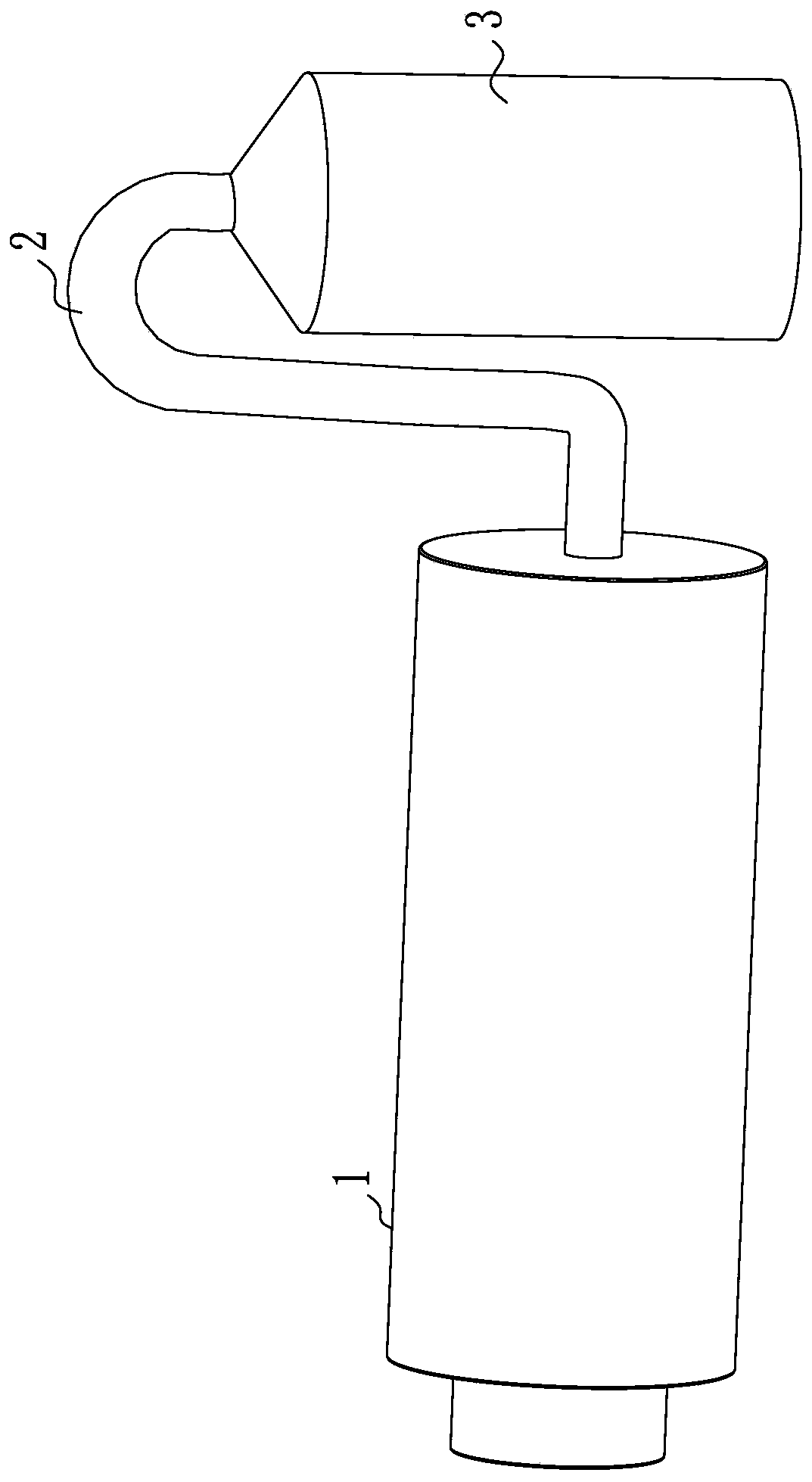
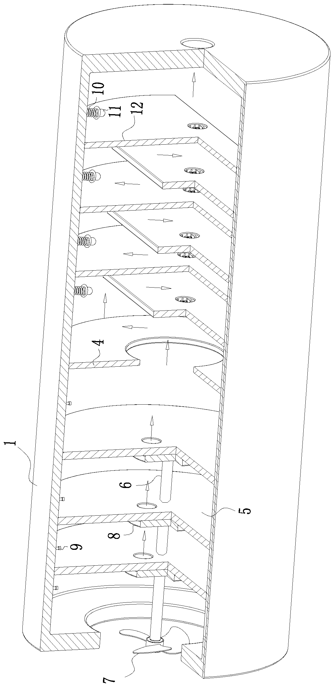
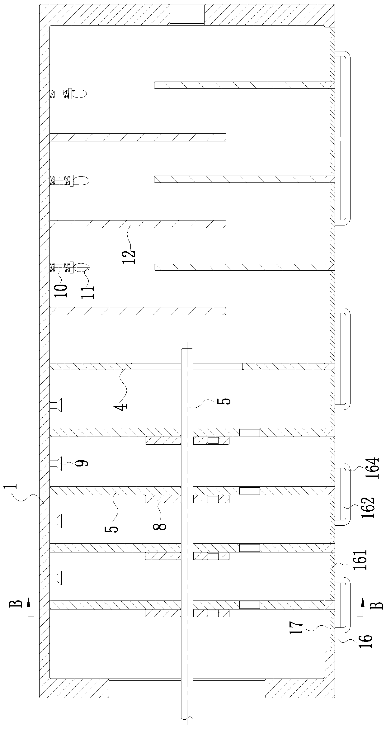
[0027] Such as Figure 1 to Figure 6As shown, a chemical waste gas purification treatment device according to the present invention includes a humidification tank 1, and the two ends of the humidification tank 1 are respectively provided with an air inlet pipe and an air outlet pipe 2, and the other end of the air outlet pipe 2 is connected with a filter Tower 3, the two ends of the humidification tank 1 are respectively provided with an air inlet hole and an air outlet hole, the middle part of the inner cavity of the humidification tank 1 is fixed with a partition 4, and the middle part of the partition board 4 is provided with a ventilation hole, and the humidification tank 1 The inner cavity is provided with more than two circular plates 5, and...


PUM


Abstract

The invention belongs to the technical field of purification of chemical exhaust gas, and particular.y relates to a device for purifying treatment of chemical exhaust gas. The device includes a humidification tank, wherein an air inlet pipe and an air outlet pipe are arranged at two ends of the humidification tank separately, the other end of the air outlet pipe is connected with a filter tower, and an air inlet hole and an air outlet hole are formed in both ends of the humidification tank; a partition plate is fixed in the middle of the inner cavity of the humidification tank, a ventilation hole is formed in the middle of the partition plate, and two or more circular plates are arranged in the inner cavity of the humidification tank; and circular holes are formed in the circular plates, and rotating shafts are rotatably connected among the circular plates. Nozzles, ultraviolet lamps and other structures are arranged, the exhaust gas is humidified through the nozzles in the process ofpassing through the humidification tank of exhaust gas, and then particulate impurities inside the humidification tank can be cleaned up quickly through a slag discharge unit, so that the efficiency of impurity cleaning is improved, the workload of the staff is reduced, and the efficiency of exhaust gas treatment is improved at the same time.

Description

technical field [0001] The invention belongs to the technical field of chemical waste gas purification, in particular to a chemical waste gas purification treatment device. Background technique [0002] When the concentration of volatile organic compounds in the air is too high, chemical waste gas can easily cause acute poisoning. In mild cases, headache, dizziness, coughing, nausea, vomiting, or drunkenness will occur; in severe cases, liver poisoning or even coma will occur soon. Some may also be life-threatening. Long-term living indoors polluted by volatile organic compounds can cause chronic poisoning, damage the liver and nervous system, cause general weakness, drowsiness, and itchy skin. Some may also cause endocrine disorders and affect sexual function; benzene and xylene can also damage the system and even cause leukemia. [0003] Chemical waste gas is usually purified by biofilm technology. Before the treatment, the waste gas needs to be pressurized and pre-wette...

Claims


Application Information

Patent Timeline
Patent Type & Authority Applications(China)
IPC IPC(8): B01D53/84B01D53/44
CPCB01D53/84B01D53/44B01D2257/708Y02A50/20
Inventor 不公告发明人
Owner 上海安居乐环保科技股份有限公司
Features
  • Generate Ideas
  • Intellectual Property
  • Life Sciences
  • Materials
  • Tech Scout
  • Unparalleled Data Quality
  • Higher Quality Content
  • 60% Fewer Hallucinations
Learn More