Low-profile ultra-wideband microstrip antenna

A microstrip antenna and ultra-wideband technology, applied in antennas, resonant antennas, antenna grounding devices, etc., can solve the problems that it is difficult to meet the needs of broadband applications, only a few tenths of a percent, and a few percent of the width, etc. Achieve the effects of simple structure, reduced energy reflection, and low cost

Inactive Publication Date: 2020-01-03
CHANGZHOU RUISHENAN MEDICAL DEVICES
View PDF9 Cites 0 Cited by
  • Summary
  • Abstract
  • Description
  • Claims
  • Application Information

AI Technical Summary

Problems solved by technology

Among them, the 915MHz frequency band of wireless communication has a wavelength of 327.9mm, so the antenna of this frequency band has the disadvantages of complex structure, large size and large profile
The widely used microstrip antenna has the characteristics of narrow bandwidth due to its inherent nature, especially the microstrip antenna whose operating frequency is below 1 GHz, its relative bandwidth is only a few percent, and the relative bandwidth of some microstrip antennas is even only a hundred. A few tenths, it is difficult to meet the application requirements of broadband

Method used


Image

  • Low-profile ultra-wideband microstrip antenna
  • Low-profile ultra-wideband microstrip antenna
  • Low-profile ultra-wideband microstrip antenna

Examples


Embodiment

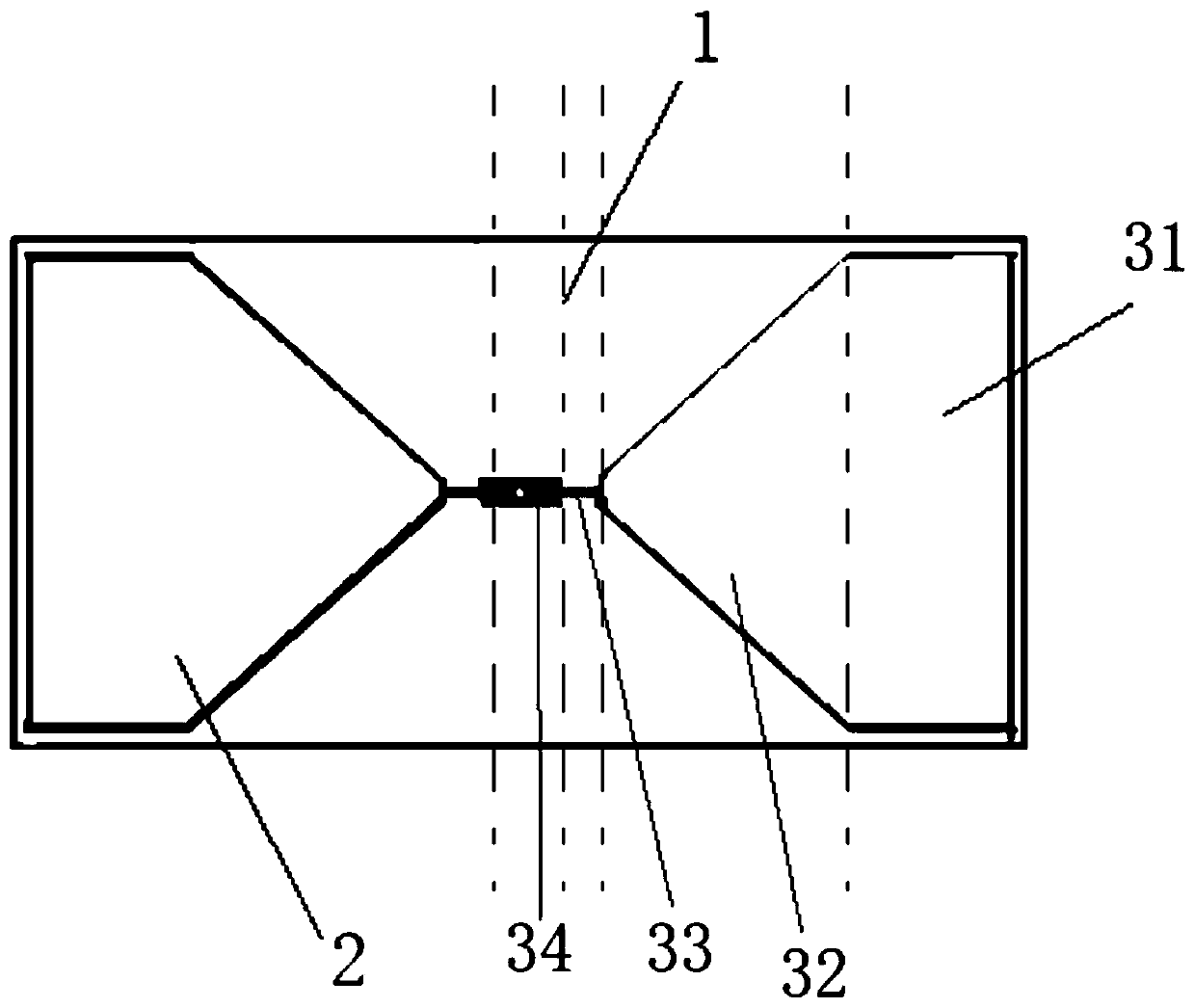
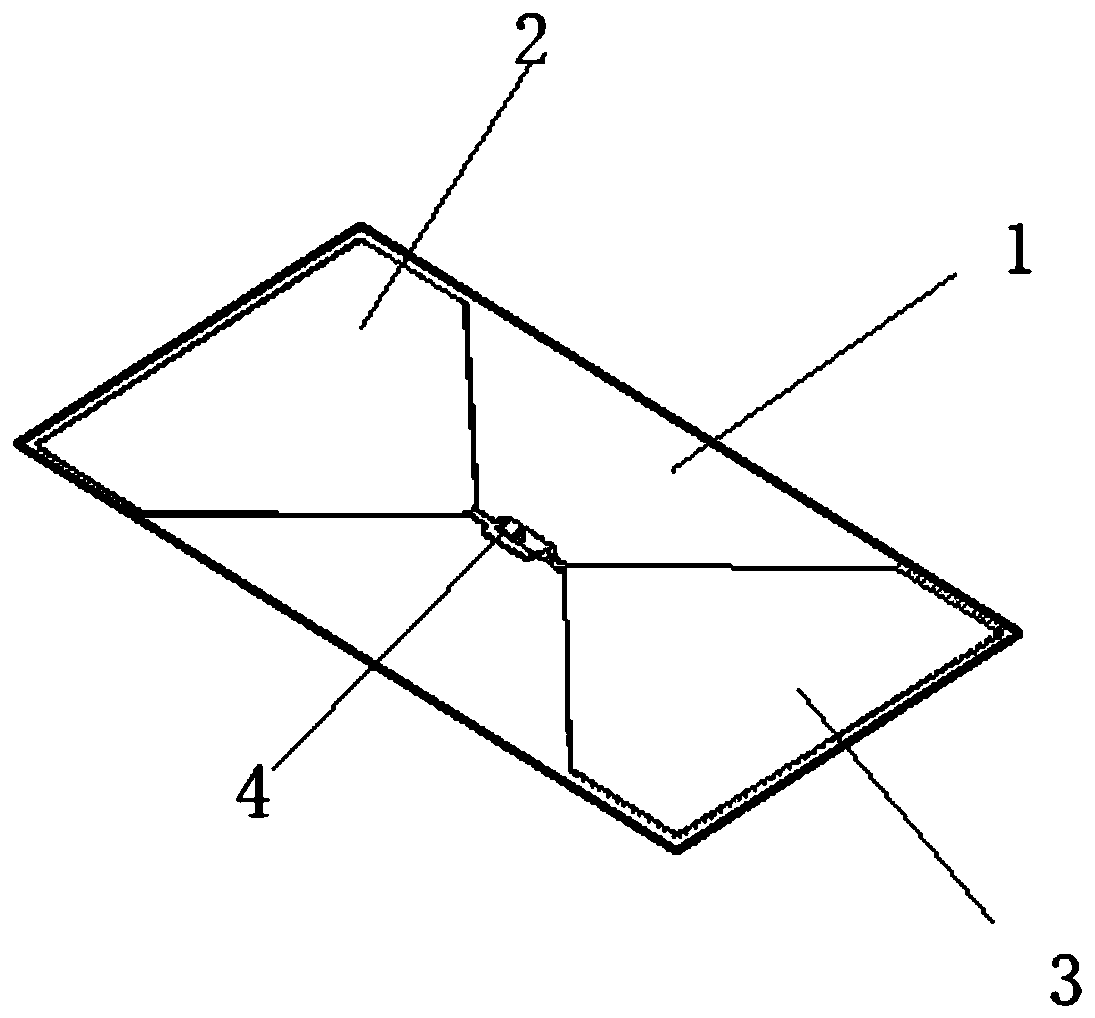
[0042] This embodiment provides a low-profile ultra-wideband microstrip antenna, such as figure 1 with figure 2 shown, including:

[0043] The intermediate dielectric plate 1, the first metal patch 2 and the second metal patch 3 respectively attached to the two sides of the intermediate dielectric plate 1, the first metal patch 2 and the second metal patch 3 are distributed in the middle Both ends of the dielectric board 1;

[0044] The first metal patch 2 and the second metal patch 3 respectively form a feeding patch part 34 and a slender microstrip line from one end close to the middle of the intermediate dielectric plate 1 to the other end away from the middle of the intermediate dielectric plate 1. Part 33, gradient microstrip patch part 32 and rectangular microstrip patch part 31;

[0045] Wherein the width of feed patch part 34 ( figure 1 The upper and lower directions are width, and the left and right directions are length) greater than the width of the elongated m...


PUM


Abstract

The invention relates to a low-profile ultra-wideband microstrip antenna. The low-profile ultra-wideband microstrip antenna comprises a middle dielectric slab and two metal patches with an overlappedpart, and the overlapped part is equivalent to capacitive loading to an antenna so as to counteract the inductive part of the impedance of the antenna. The adjustment of the overlapping length of thepart is equivalent to adjustment of equivalent capacitance, and input impedance can be microadjusted. When the equivalent capacitance is opposite to the equivalent inductance part of the antenna, theinput impedance of the antenna can be a required value, the energy reflection of the antenna is reduced, and the radiation efficiency of the antenna is improved. A gradient microstrip patch part and arectangular microstrip patch part can slowly change the input impedance of the antenna under the feeding of signals with different frequencies. A slender microstrip line part can be used for adjusting the resonant frequency of the antenna to make the antenna work near a certain center frequency. The gradient microstrip line structure can realize that the path through which the current flows is close to a quarter wavelength under different input frequency signals, and the input impedance of the antenna is close to a certain value in a large frequency range.

Description

technical field [0001] The invention relates to the antenna field of wireless communication, in particular to a low-profile ultra-wideband microstrip antenna. Background technique [0002] With the development of wireless communication technology, the application fields of antennas are also increasing. Different signal frequency bands and application fields require different types of antennas. Among them, the 915MHz frequency band of wireless communication has a wavelength of 327.9mm, so the antenna of this frequency band has the disadvantages of complex structure, large size and large profile. The widely used microstrip antenna has the characteristics of narrow bandwidth due to its inherent properties, especially the microstrip antenna whose operating frequency is below 1 GHz, its relative bandwidth is only a few percent, and the relative bandwidth of some microstrip antennas is even only a hundred. A few tenths, it is difficult to meet the application requirements of bro...

Claims


Application Information

Patent Timeline
Patent Type & Authority Applications(China)
IPC IPC(8): H01Q1/38H01Q1/48H01Q1/50H01Q5/335H01Q9/04
CPCH01Q1/38H01Q1/48H01Q1/50H01Q9/045H01Q5/335
Inventor 杜卫张新国杜玉惠
Owner CHANGZHOU RUISHENAN MEDICAL DEVICES
Why Eureka
Try Eureka