Doubly-fed induction generator fault detection method based on sliding mode observer

A doubly-fed induction motor and sliding mode observer technology, which is applied in the direction of motor generator testing, control generator, motor generator control, etc., can solve problems affecting system reliability, etc., and achieve simple structure and strong anti-interference ability Effect

Active Publication Date: 2020-01-03
HUNAN UNIV OF SCI & TECH
View PDF6 Cites 12 Cited by
  • Summary
  • Abstract
  • Description
  • Claims
  • Application Information

AI Technical Summary

Problems solved by technology

[0004] The purpose of the present invention is to solve the problem that the reliability of the entire system is affected by the voltage drop, the short circuit between the stator turns and the failure of the...

Method used


Image

  • Doubly-fed induction generator fault detection method based on sliding mode observer
  • Doubly-fed induction generator fault detection method based on sliding mode observer
  • Doubly-fed induction generator fault detection method based on sliding mode observer

Examples


specific Embodiment approach 1

[0024] Specific embodiment one: the doubly-fed induction generator fault detection method based on sliding mode observer described in this implementation method, it comprises the following steps:

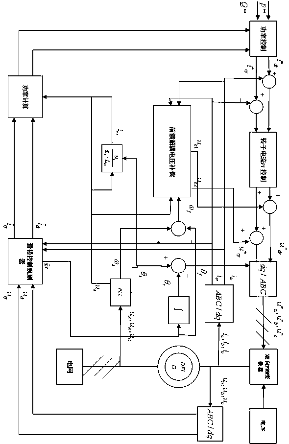
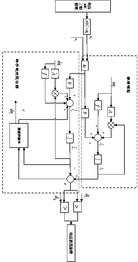
[0025] Step 1. The stator side of the doubly-fed induction motor is connected to the grid terminal, and the stator voltage signal can be obtained through the voltage sensor , the stator current signal can be obtained through the current sensor , the rotor side of the doubly-fed induction motor is connected to the back-to-back power converter and the rotor voltage signal can be obtained through the voltage sensor , the rotor current signal can be obtained through the current sensor ;

[0026] Step 2: Transform the stator and rotor voltage signals through clark and park to obtain synchronous rotation Stator and rotor voltage signal in the coordinate system , at the same time, the stator and rotor current signals are transformed by clark and park to obtain synchronous rotatio...

specific Embodiment approach 2

[0034] Specific embodiment two: this embodiment is a further limitation of the sliding mode observer-based doubly-fed induction generator fault detection method described in specific embodiment one,

[0035] In step 3, according to the voltage equation and the flux equation of the double-fed motor, the method of establishing the state space equation is as follows:

[0036] The voltage equation is:

[0037] ,

[0038] ,

[0039] The flux linkage equation is:

[0040] ,

[0041] ,

[0042] ,

[0043] In the formula, respectively The stator and rotor voltage vectors of the shaft, respectively The stator and rotor current vectors of the shaft, respectively The flux vectors of the stator and rotor of the shaft, are the rotor and stator resistances, respectively, are the self-inductance of the stator and rotor, respectively, is the mutual inductance between the stator and rotor, are the leakage inductance of the stator and rotor, respectively, are ...

specific Embodiment approach 3

[0048] Specific embodiment three: this embodiment is a further limitation of the sliding mode observer-based doubly-fed induction generator fault detection method described in specific embodiment one,

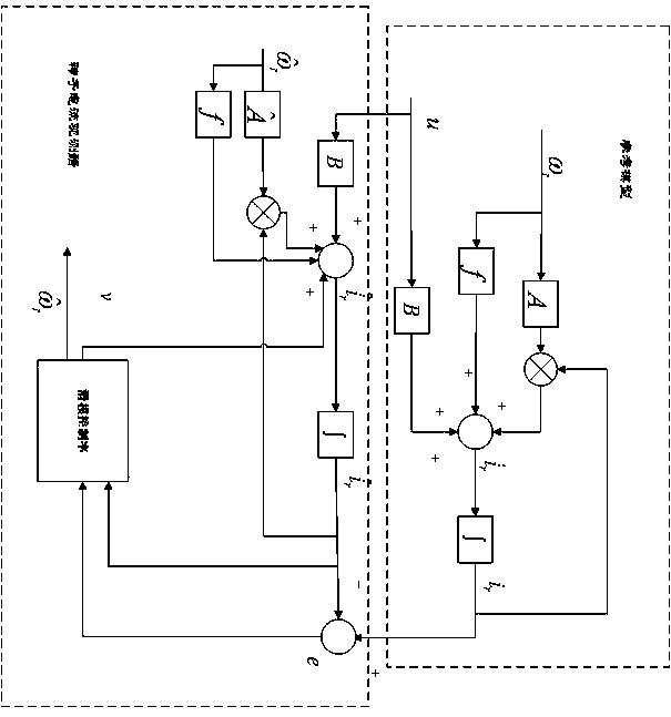
[0049] In step 4, when only the rotor current state space model is considered, the stator voltage oriented control method is used to obtain the relationship between the stator current item and the rotor current item, and the method to obtain the state equation without the stator current item is:

[0050] The stated only considers the stator current When the state space model is used, its state space model is:

[0051]

[0052] In the formula, , , , , , , , respectively The stator and rotor voltage vectors of the shaft, respectively The stator and rotor current vectors of the shaft, are the rotor and stator resistances, respectively, are the self-inductance of the stator and rotor, respectively, is the mutual inductance between the stator and roto...


PUM


Abstract

In order to carry out fault detection on the doubly-fed induction generator, the invention provides a doubly-fed induction generator fault detection method based on a sliding mode observer. Because asliding mode observer is simple in structure, is not liable to be affected by parameters, is high in anti-interference capability, and the like, the sliding mode observer is used for the fault detection of the doubly-fed induction generator. Firstly, a sliding mode observer is built according to a mathematical model of the doubly-fed induction generator, the rotor current and the rotating speed ofthe doubly-fed induction generator are observed, and self-detection of faults is achieved by comparing the residual error between the actual rotor current value and the observed value, then three faults of a power grid end voltage drop fault, a doubly-fed induction generator stator turn-to-turn fault and a rotor current sensor fault are given so as to prove that the sliding-mode observer can wellperform fault detection on faults occurring at different positions, and the sliding-mode observer has the characteristics of the high response speed, the good stability and the like.

Description

technical field [0001] The invention relates to a double-fed induction motor fault detection method based on a sliding mode observer, which belongs to the field of electric control. Background technique [0002] As a new form of power generation, wind power has been connected to the power grid on a large scale, which has changed the stable operation characteristics of the traditional power system dominated by synchronous generators. With the vigorous development of wind power generation, the total installed capacity of wind power has grown rapidly, and the capacity of single units has continued to increase. The proportion of installed wind power generation in the total installed capacity of the power system has continued to increase, especially in some areas with abundant wind energy resources and concentrated wind power installed capacity. , wind power generation has occupied an important position in the local power system, and has become an important power injection node o...

Claims


Application Information

Patent Timeline
IPC IPC(8): H02P21/00H02P21/13H02P21/14H02P21/24H02P21/22G01R31/34
CPCG01R31/34H02P21/0007H02P21/13H02P21/14H02P21/22H02P21/24
Inventor 蒋丹于文新王俊年
Owner HUNAN UNIV OF SCI & TECH
Why Eureka
Try Eureka