Low-power rail-to-rail drive amplifier circuit

A technology for driving amplifiers and amplifiers, which is applied in the direction of amplifiers, amplifier combinations, and improved amplifiers to improve efficiency. It can solve the problems of high power consumption of the circuit and difficulty in meeting the needs of radar system miniaturization and integration, and achieve strong drive capabilities. , low power consumption, and great adjustability

Active Publication Date: 2020-01-03
CHINA ELECTRONICS TECH GRP CORP NO 14 RES INST
View PDF2 Cites 0 Cited by
  • Summary
  • Abstract
  • Description
  • Claims
  • Application Information

AI Technical Summary

Problems solved by technology

The traditional power amplifier gate drive chip circuit has high power consumption, and the drive capability is difficult to meet the requirements of miniaturization and integration of the radar system under the same hardware consumption.

Method used


Image

  • Low-power rail-to-rail drive amplifier circuit
  • Low-power rail-to-rail drive amplifier circuit

Examples


Embodiment Construction

[0020] Through the following examples, combined with the attached Figure 1-2 , the technical solution of the present invention will be further specifically described.

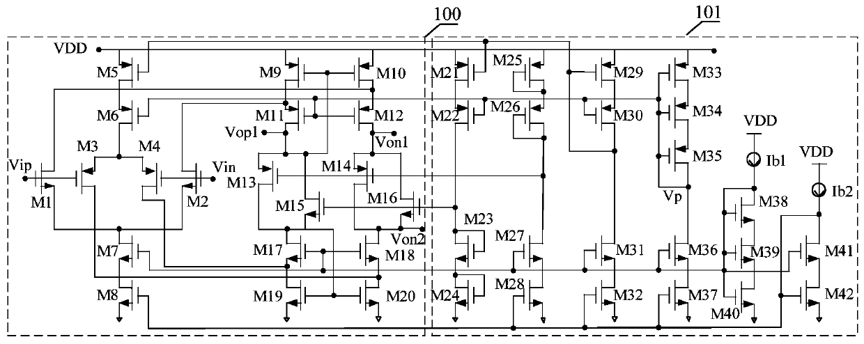
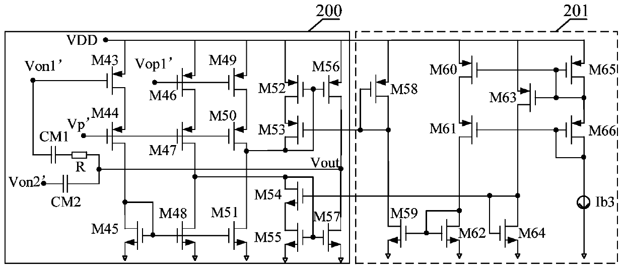
[0021] as attached Figure 1-2 As shown, a rail-to-rail driver amplifier circuit adopts a three-stage operational amplifier structure, including a first-stage amplifier 100 , a first-stage amplifier bias circuit 101 , a driver-stage amplifier 200 and a driver-stage amplifier bias circuit 201 .

[0022] Wherein, the first-stage amplifier 100 adopts the rail-to-rail input amplifier of the prior art, which is used to provide the main gain of the rail-to-rail drive amplifier circuit of the present invention, and simultaneously realize the input voltage range from rail to rail; and is provided with output terminals Vop1, Von1, Von2. The first-stage amplifier bias circuit 101 adopts the bias circuit of the prior art, and the first-stage amplifier bias circuit provides two-way reference currents by the reference so...


PUM


Abstract

The invention provides a low-power-consumption rail-to-rail driving amplifier circuit. The low-power-consumption rail-to-rail driving amplifier circuit comprises a first-stage amplifier, a first-stageamplifier biasing circuit, a driving-stage amplifier and a driving-stage amplifier biasing circuit; the first-stage amplifier is connected with the driving-stage amplifier through an end point; the driving-stage amplifier comprises a compensation capacitor CM1, a compensation capacitor CM2 and a compensation resistor R and is used for carrying out Miller compensation; the driving stage amplifiercomprises MOS transistors M44, M47 and M50 and is used for reducing the influence of mismatch on the driving capability; the driving stage amplifier comprises MOS tubes M56 and M57 and is used for reducing static power consumption. According to the amplifier disclosed by the invention, rail-to-rail input is realized, and high-current driving output is met; capacitors CM1 and CM2 and a resistor R are adopted to carry out Miller compensation; a matching transistor is added to the dynamic output stage, so that the output stage gain is increased while mismatch is reduced; a high-threshold N tube and a high-threshold P tube are adopted, and static power consumption is reduced compared with a traditional driving amplifier.

Description

technical field [0001] The invention relates to the field of circuit design, in particular to a low power consumption rail-to-rail drive amplifier circuit. Background technique [0002] With the development of radar system miniaturization and integration requirements, the hardware consumption requirements for highly integrated fronts are becoming more and more stringent. There are many types of gate drive chips for power amplifiers in existing radar systems, the driving voltage range covered is getting wider and higher, and the driving capability requirements are getting higher and higher. The traditional class AB amplifier adopts rail-to-rail input and simple class AB output structure. If it is to realize high current drive, the static power consumption is relatively high. The traditional power amplifier gate drive chip circuit has high power consumption, and the drive capability cannot meet the requirements of the miniaturization and integration of the radar system under ...

Claims


Application Information

Patent Timeline
Patent Type & Authority Applications(China)
IPC IPC(8): H03F1/02H03F3/68
CPCH03F1/0222H03F3/68
Inventor 徐宏林张浩刘海涛吴俊杰
Owner CHINA ELECTRONICS TECH GRP CORP NO 14 RES INST
Why Eureka
Try Eureka