Power battery pack heat dissipation device with heat pipe device and heat dissipation method thereof

A technology for power battery packs and heat sinks, which is applied to secondary batteries, battery pack components, circuits, etc. It can solve problems such as increasing battery temperature inconsistency, shortening battery life, and large temperature gradients in battery packs to improve temperature. Uneven distribution, increase temperature consistency, and improve the effect of heat dissipation

Active Publication Date: 2020-01-07
SOUTH CHINA UNIV OF TECH
View PDF5 Cites 6 Cited by
  • Summary
  • Abstract
  • Description
  • Claims
  • Application Information

AI Technical Summary

Problems solved by technology

[0004] At present, the forced air cooling used for battery packs generally adopts one-way air cooling, which will cause a large temperature gradient inside the battery pack, increase the inconsistency of battery temperature, shorten the service life of the battery, and reduce the performance of the battery pack.

Method used


Image

  • Power battery pack heat dissipation device with heat pipe device and heat dissipation method thereof
  • Power battery pack heat dissipation device with heat pipe device and heat dissipation method thereof
  • Power battery pack heat dissipation device with heat pipe device and heat dissipation method thereof

Examples


Embodiment Construction

[0033] The present invention will be further described below in conjunction with drawings and embodiments.

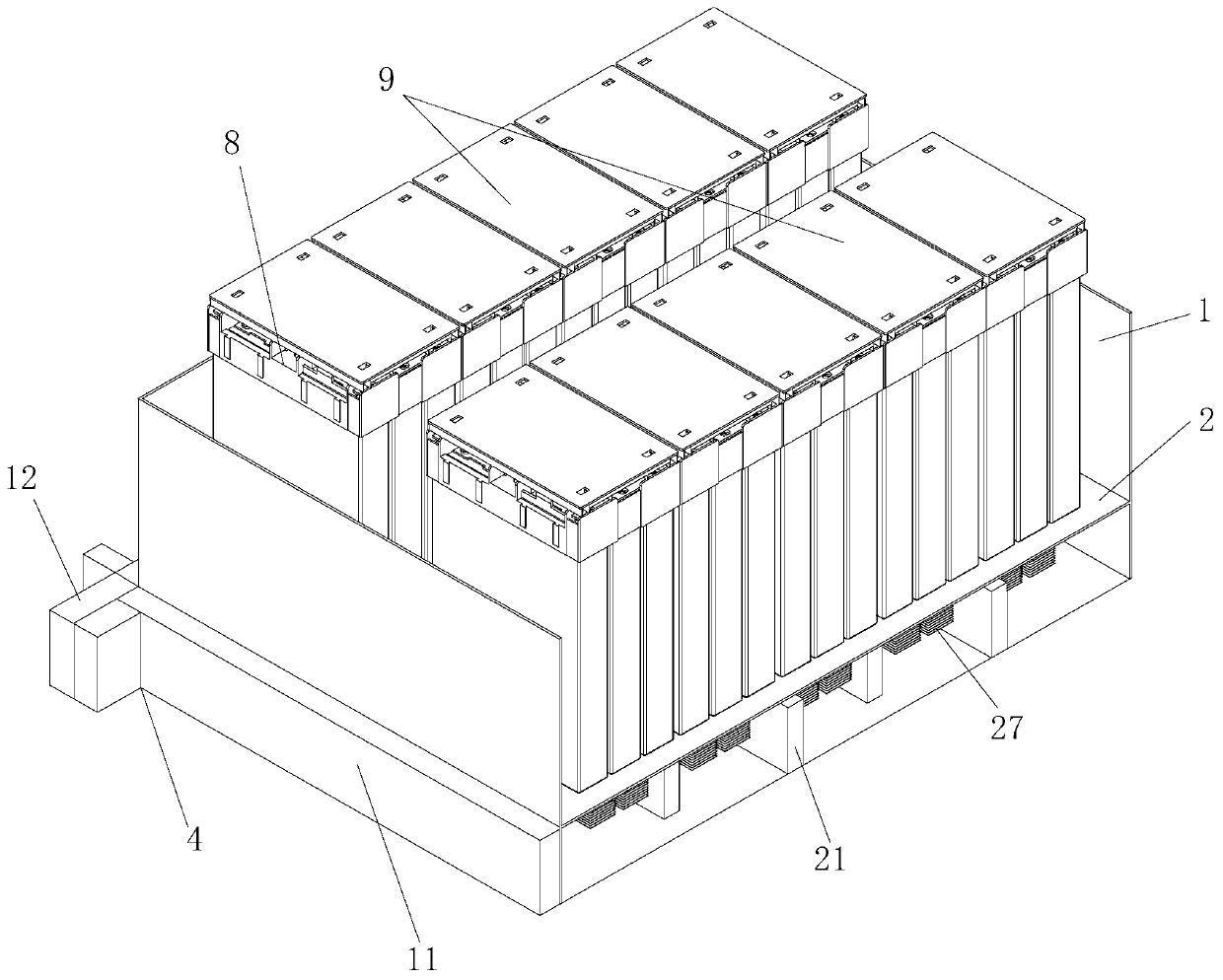
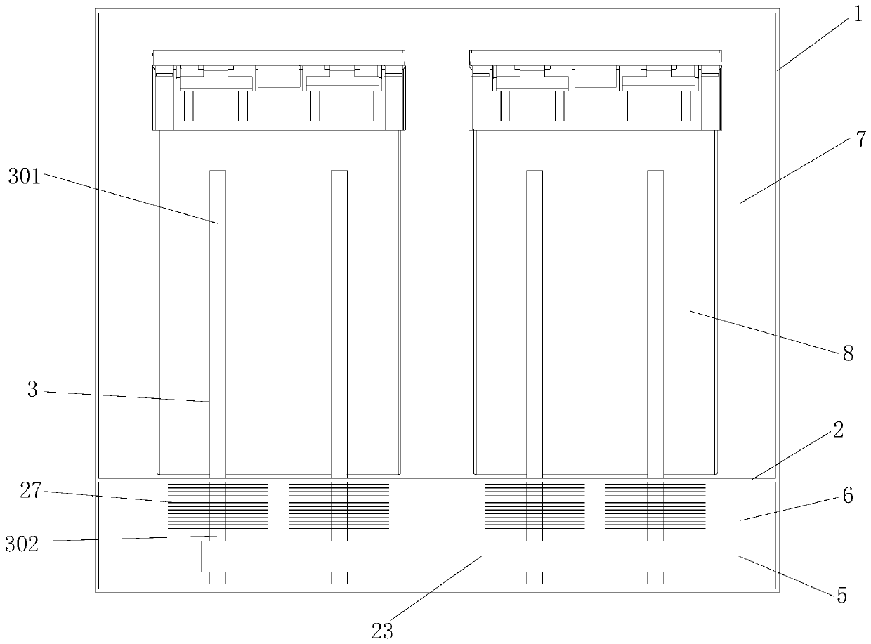
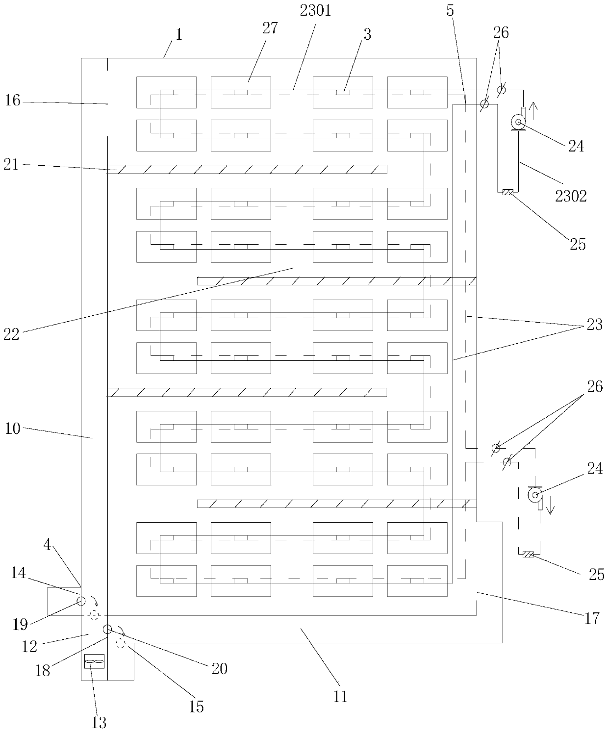
[0034] Such as Figure 1 to Figure 3 The heat dissipation device for the power battery pack shown with the heat pipe device includes a casing, a partition, a heat dissipation heat pipe, an air cooling mechanism, and a water cooling mechanism. cavity, the evaporating end of the heat dissipation heat pipe is closely attached to the electric core located in the heating cavity, the cooling end of the heat dissipation heat pipe passes through the partition and then extends into the heat dissipation cavity; the air cooling mechanism is installed on the outside of the shell, and the The heat dissipation air channel of the air cooling mechanism communicates with the heat dissipation cavity; the water cooling mechanism is connected with the cooling end of the heat dissipation heat pipe.

[0035] Specifically, such as figure 1 and figure 2 As shown, the partition divides the ...


PUM


Abstract

The invention discloses a power battery pack heat dissipation device with a heat pipe device. The power battery pack heat dissipation device comprises a housing, a separator plate, a heat dissipationheat pipe, an air cooling mechanism and a water cooling mechanism. The inner cavity of the housing is divided into a heat dissipation cavity and a heating cavity for holding a battery core through theseparator plate; the evaporation end of the heat dissipation heat pipe is tightly attached to the battery core located in the heating cavity; the cooling end of the heat dissipation heat pipe runs through the separator plate and then, stretches into the heat dissipation cavity; the air cooling mechanism is installed on the outer side of the housing, and a heat dissipation air duct of the air cooling mechanism communicates with the heat dissipation cavity; and the water cooling mechanism is connected with the cooling end of the heat dissipation heat pipe. Meanwhile, the invention further discloses a heat dissipation method of the power battery pack heat dissipation device with the heat pipe device. Moisture and dusts in air can be prevented from being attached to the surface of the battery, so that the battery is protected, and the performance of the battery is guaranteed; and meanwhile, different working modes can be adopted in the heat dissipation process, and the effects of energy conservation and emission reduction are achieved under the condition that the heat dissipation efficiency is guaranteed.

Description

technical field [0001] The invention relates to the technical field of batteries, in particular to a heat dissipation device for a power battery pack with a heat pipe device and a heat dissipation method thereof. Background technique [0002] As one of the key components of electric vehicles, the power battery is responsible for energy storage and supply; the power battery will generate a lot of heat during charging and discharging, which will not only affect the life of the battery itself, but also affect the performance of the vehicle. And the safety of passengers brings hidden dangers; therefore, the heat dissipation problem of the power battery during use is one of the key contents of the electric vehicle technology research. [0003] The traditional way of forced air cooling of battery packs is to take away the heat generated by air flowing over the surface of the battery cells. In this heat dissipation mode, the air flow used for heat dissipation is in direct contact ...

Claims


Application Information

Patent Timeline
Patent Type & Authority Applications(China)
IPC IPC(8): H01M2/10H01M10/613H01M10/617H01M10/625H01M10/633H01M10/647H01M10/6552H01M10/6556H01M10/6563H01M10/6568H01M50/249
CPCH01M10/613H01M10/625H01M10/633H01M10/617H01M10/647H01M10/6556H01M10/6563H01M10/6568H01M10/6552H01M50/20Y02E60/10
Inventor 陈吉清蒋心平李屹罡兰凤崇
Owner SOUTH CHINA UNIV OF TECH
Why Eureka
Try Eureka