Positioning and cutting edge grinding device for round glass

A technology for positioning cutting and edging equipment, used in grinding/polishing equipment, stone processing equipment, metal processing equipment, etc., can solve the problems of increasing production risks, insufficient glass edges and corners, low precision, etc., to reduce manual operations. risk, increase production safety, and improve product quality.

Active Publication Date: 2020-01-10
福州宏毓建材有限公司
View PDF6 Cites 4 Cited by
  • Summary
  • Abstract
  • Description
  • Claims
  • Application Information

AI Technical Summary

Problems solved by technology

[0003] Round glass is a glass shape that can be used in glasses, instruments or curtain walls, etc. The existing round glass needs to be measured before cutting, the precision is not high, and the operation is more cumbersome, and the production efficiency is low. The glass cannot be fixed well during cutting, and there are certain errors. After cutting, the glass corners are not smooth enough and appear sharp. In the prior art, the cut circular glass needs to be manually transported to the next station. Because of its sharp corners, it is easy to be cut by manual operation, which increases the safety risk. In the prior art, the glass slag generated by cutting is not treated in a centralized manner, which pollutes the production environment and increases the production risk.

Method used


Image

  • Positioning and cutting edge grinding device for round glass
  • Positioning and cutting edge grinding device for round glass
  • Positioning and cutting edge grinding device for round glass

Examples


Embodiment Construction

[0032] The technical solutions of the present invention will be further described below in conjunction with the accompanying drawings and through specific implementation methods.

[0033] Wherein, the accompanying drawings are only for illustrative purposes, showing only schematic diagrams, rather than physical drawings, and should not be construed as limitations on this patent; in order to better illustrate the embodiments of the present invention, some parts of the accompanying drawings will be omitted, Enlargement or reduction does not represent the size of the actual product; for those skilled in the art, it is understandable that certain known structures and their descriptions in the drawings may be omitted.

[0034] In the drawings of the embodiments of the present invention, the same or similar symbols correspond to the same or similar components; , "inner", "outer" and other indicated orientations or positional relationships are based on the orientations or positional ...


PUM


Abstract

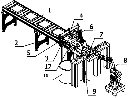
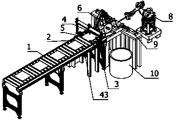
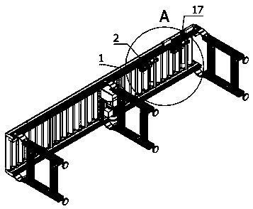
The invention relates to the field of machining, and particularly relates to a positioning and cutting edge grinding device for round glass. The positioning and cutting edge grinding device comprisesa roller conveyor, a first material blocking assembly, a cutting positioning assembly, an annular cutting assembly, a fragment breaking assembly, a material taking manipulator, a rotary table, an edgegrinding manipulator capable of polishing round glass epitaxy at multiple angles, two-group grinding and positioning assemblies and a material receiving box, the grinding and positioning assemblies are symmetrically arranged on the two sides of the rotary table, the material receiving box is arranged at the side of the rotary table, the first material blocking assembly is arranged in the middle of the roller conveyor in a lifting manner, the cutting and positioning assembly is arranged at the output end of the roller conveyor in a lifting manner, the annular cutting assembly is arranged justabove the output end of the roller conveyor in a lifting mode. According to the positioning and cutting edge grinding device, full-automatic production is achieved through positioning and cutting edgegrinding device of the round glass, a series of operations such as cutting, edge grinding, chamfering and the like can be performed on the glass to be processed, the glass to be processed can be accurately positioned, and the glass waste residues can be subjected to centralized recycling treatment.

Description

technical field [0001] The invention relates to the field of mechanical processing, in particular to a positioning cutting and edging equipment for circular glass. Background technique [0002] With the industrialization and scale of glass production, glasses with various uses and performances have come out one after another; in modern times, glass has become an important material in daily life, production and science and technology. [0003] Round glass is a glass shape that can be used in glasses, instruments or curtain walls, etc. The existing round glass needs to be measured before cutting, the precision is not high, and the operation is more cumbersome, and the production efficiency is low. The glass cannot be fixed well during cutting, and there are certain errors. After cutting, the glass corners are not smooth enough and appear sharp. In the prior art, the cut circular glass needs to be manually transported to the next station. Because of its sharp edges and corners...

Claims


Application Information

Patent Timeline
Patent Type & Authority Applications(China)
IPC IPC(8): B24B9/08B24B41/00B24B41/06B24B55/12B28D1/22B28D7/04
CPCB24B9/08B24B41/005B24B41/06B24B55/12B28D1/22B28D7/04
Inventor 贾文康
Owner 福州宏毓建材有限公司
Why Eureka
Try Eureka