Wastewater treatment device and method

A wastewater treatment and wastewater technology, applied in multi-stage water treatment, water/sewage multi-stage treatment, water/sludge/sewage treatment, etc., can solve the problems of complex structure, high construction cost, poor oil absorption effect, etc. The effect of oil pollution content, expansion of water flow area, and simple structure

Pending Publication Date: 2020-01-10
中国电建集团海外投资有限公司
View PDF1 Cites 2 Cited by
  • Summary
  • Abstract
  • Description
  • Claims
  • Application Information

AI Technical Summary

Problems solved by technology

[0005] Therefore, the technical problem to be solved by the present invention is to overcome the defects of complex structure, high construction cost and poor oil absorption effect in the prior art of sewage treatment equipment, so as to provide a sewage treatment equipment and method

Method used


Image

  • Wastewater treatment device and method
  • Wastewater treatment device and method
  • Wastewater treatment device and method

Examples


Embodiment 1

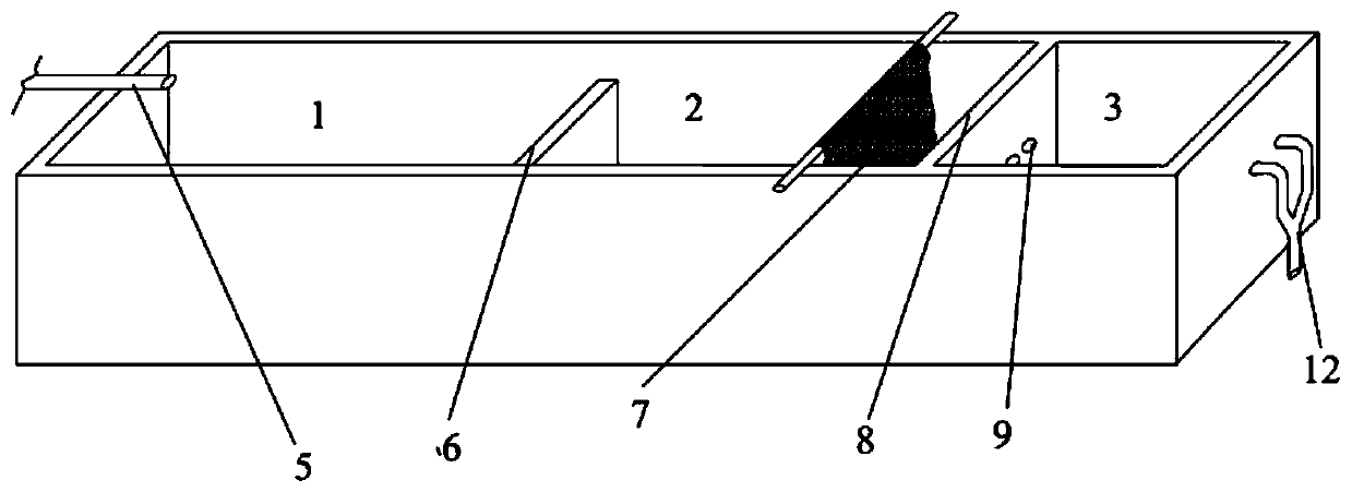
[0044] This embodiment provides a wastewater treatment device, its three-dimensional structure is shown in figure 1 , specifically including,

[0045] Water inlet 5, first sedimentation tank 1, second sedimentation tank 2, third sedimentation tank 3, first partition wall 6, oil absorbing device (this embodiment is oil-absorbing geotextile) 7, second partition wall 8, first channel The hole 9 and the water outlet 12, the water inlet is arranged on the top of the side wall of the first sedimentation tank, the water outlet is arranged on the side wall of the third sedimentation tank, and the first sedimentation tank and the second sedimentation tank are separated by the first partition wall , the second sedimentation tank and the third sedimentation tank are separated by the second partition wall, the second partition wall is provided with the first through hole, and the second sedimentation tank is provided with 2 oil-absorbing geotextiles, and the oil-absorbing geotextiles adop...

Embodiment 2

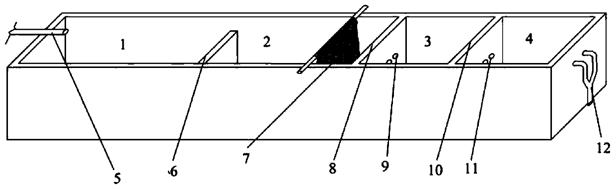
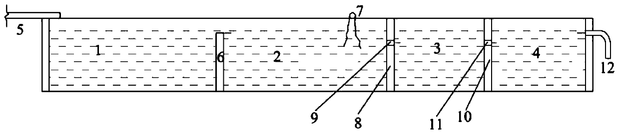
[0048] This embodiment provides a wastewater treatment device, its three-dimensional structure is shown in figure 2 , front view see image 3 , top view see Figure 4 , specifically including,

[0049] Water inlet 5, first sedimentation tank 1, second sedimentation tank 2, third sedimentation tank 3, fourth sedimentation tank 4, first partition wall 6, oil absorption device (this embodiment is oil absorption geotextile) 7, second partition Wall 8, the third partition wall 10, the first through hole 9, the second through hole 11 and the water outlet 12, the water inlet is arranged on the top of the side wall of the first sedimentation tank, the fourth sedimentation tank is connected in series with the third sedimentation tank, the second The third sedimentation tank and the fourth sedimentation tank are used to settle fine particles, the water outlet is set on the side wall of the fourth sedimentation tank, the first sedimentation tank and the second sedimentation tank are sep...

Embodiment 3

[0052] This embodiment provides a wastewater treatment device, which specifically includes:

[0053] Water inlet 5, first sedimentation tank 1, second sedimentation tank 2, third sedimentation tank 3, fourth sedimentation tank 4, first partition wall 6, oil absorption device (this embodiment is oil absorption geotextile) 7, second partition Wall 8, the third partition wall 10, the first through hole 9, the second through hole 11 and the water outlet 12, the water inlet is arranged on the top of the side wall of the first sedimentation tank, the fourth sedimentation tank is connected in series with the third sedimentation tank, the second The third sedimentation tank and the fourth sedimentation tank are used to settle fine particles, the water outlet is set on the side wall of the fourth sedimentation tank, the first sedimentation tank and the second sedimentation tank are separated by the first partition wall, the second sedimentation tank and the second sedimentation tank Th...


PUM

PropertyMeasurementUnit
heightaaaaaaaaaa
heightaaaaaaaaaa
heightaaaaaaaaaa

Abstract

The invention belongs to the technical field of wastewater treatment, and particularly relates to a wastewater treatment device and a method. The wastewater treatment device comprises a first sedimentation tank for settling large particles, a second sedimentation tank for removing oil stains in wastewater and a third sedimentation tank for settling fine particles; the device is integrally arranged; the height of a first partition wall is limited, so that the height is lower than the height of the wastewater surface; and the communication with the first sedimentation tank and the second sedimentation tank is adopted; the water flow area can be enlarged; water flow velocity is reduced, particles in the wastewater are precipitated in the first sedimentation tank and the second sedimentation tank to the maximum extent, at the same time, water waves can be transmitted from the first sedimentation tank to the second sedimentation tank, the oil stain floating on the wastewater surface is adsorbed in an oil adsorption device by the pushing force of the water waves, and the oil stain adsorption effect can be improved without additional external force; the third sedimentation tank can be used for precipitating fine particles again, so that the purpose of removing the fine particles is achieved.

Description

technical field [0001] The invention belongs to the technical field of wastewater treatment, and in particular relates to a wastewater treatment device and method. Background technique [0002] A hydropower station is a comprehensive engineering facility that converts water energy into electrical energy, also known as a hydropower plant. It includes a series of hydropower station buildings and various hydropower station equipment installed to produce electricity from water energy. During the construction of hydropower stations, the waste water produced has many types, large volume and high concentration of suspended solids. If it is discharged directly without treatment, it will adversely affect the ecological environment of the construction area and the water quality of the downstream river. [0003] The sewage and wastewater generated by hydropower stations are divided into construction period wastewater and operation period wastewater according to time periods, and are di...

Claims


Application Information

Patent Timeline
Patent Type & Authority Applications(China)
IPC IPC(8): C02F9/02C02F1/40
CPCC02F1/40C02F2001/007C02F2301/08
Inventor 胡胜丰唐存军方平光卢营曹际宣李国锋金勇周建新
Owner 中国电建集团海外投资有限公司
Why Eureka
Try Eureka