Exhaust noise treatment device for fuel vehicles

A processing device and automobile technology, which is applied in the direction of exhaust treatment, exhaust device, noise reduction device, etc., can solve the problems that affect the efficiency of the noise reduction process, the service life of the muffler is short, and the scope of application is not wide.

Active Publication Date: 2021-04-23
HUNAN INSTITUTE OF ENGINEERING
View PDF6 Cites 0 Cited by
  • Summary
  • Abstract
  • Description
  • Claims
  • Application Information

AI Technical Summary

Problems solved by technology

[0002] The number of automobiles in our country is increasing. People's requirements for automobiles are no longer just means of transportation, but also energy-saving, environmental protection, aesthetics and comfort. The traffic noise of motor vehicles is the main source of urban road noise. Noise regulations will continue to be stricter. However, in the production and processing of general mufflers, the resistive mufflers and resistive mufflers that are mainly used in the market can only deal with high-frequency or low-frequency noise separately, and the scope of application is not wide. Wide, and as far as the resistive muffler is concerned: in high temperature, water vapor and gas that is corrosive to sound-absorbing materials, the service life of the muffler is short, and the effect on low-frequency noise is poor; the biggest disadvantage is that the power loss of the muffler is too large; and In the general single muffler filter hole, the noise treatment effect is not obvious, which in turn affects the efficiency of the entire muffler process

Method used


Image

  • Exhaust noise treatment device for fuel vehicles
  • Exhaust noise treatment device for fuel vehicles

Examples


Embodiment Construction

[0013] In order to make the purpose, technical solutions and advantages of the embodiments of the present invention clearer, the technical solutions in the embodiments of the present invention will be clearly and completely described below in conjunction with the drawings in the embodiments of the present invention. Obviously, the described embodiments It is a part of embodiments of the present invention, but not all embodiments. Based on the embodiments of the present invention, all other embodiments obtained by persons of ordinary skill in the art without creative efforts fall within the protection scope of the present invention.

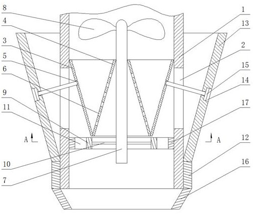
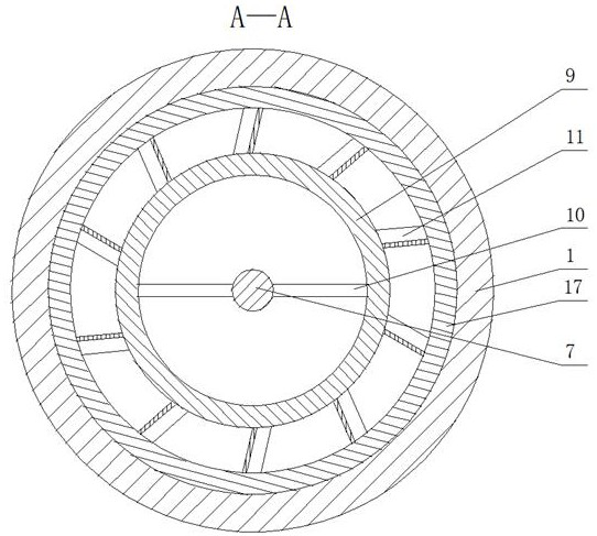
[0014] An exhaust noise treatment device for fuel vehicles, as shown in the figure, includes an exhaust pipe 1 of the automobile, a number of first through holes 2 are evenly distributed on the side of the exhaust pipe 1 along the axial direction, and a first cone is installed on the inside of the exhaust pipe 1 Shaped cylinder 3, the small end of...


PUM


Abstract

An exhaust noise treatment device for fuel vehicles, comprising an exhaust pipe of the automobile, several first through holes evenly distributed on the side of the exhaust pipe, a first conical cylinder installed inside the exhaust pipe, the large end surface of the first conical cylinder and the exhaust pipe The inside of the trachea is in contact and fit, the second cone is installed inside the first cone, the small end surface of the third cone is fixedly connected with the sleeve, and several countersunk holes are evenly opened on the outside of the third cone. The present invention is suitable for Noise reduction of automobile exhaust, the exhaust exhaust passes through the large end face of the first conical cylinder, the exhaust gas passes through the second through hole from the middle of the ring, and then is discharged into the atmosphere, followed by the exhaust emission and noise, the noise passes through the rotating The first blade reduces the energy of the sound wave, and is reflected inside the first cone, the energy of the sound wave is reduced again, thereby reducing the noise. The device has a simple structure and is easy to disassemble and assemble, which can improve the exhaust emission and improve the efficiency of the engine. , energy saving and emission reduction, reducing exhaust noise can also protect the exhaust pipe to a certain extent.

Description

technical field [0001] The invention belongs to the field of noise processing devices, in particular to an exhaust noise processing device for fuel vehicles. Background technique [0002] The number of automobiles in our country is increasing. People's requirements for automobiles are no longer just means of transportation, but also energy-saving, environmental protection, aesthetics and comfort. The traffic noise of motor vehicles is the main source of urban road noise. Noise regulations will continue to be stricter. However, in the production and processing of general mufflers, the resistive mufflers and resistive mufflers that are mainly used in the market can only deal with high-frequency or low-frequency noise separately, and the scope of application is not wide. Wide, and as far as the resistive muffler is concerned: in high temperature, water vapor and gas that is corrosive to sound-absorbing materials, the service life of the muffler is short, and the effect on low-f...

Claims


Application Information

Patent Timeline
Patent Type & Authority Patents(China)
IPC IPC(8): F01N13/18F01N13/08F01N1/00F01N1/18F01N1/08F01N1/06
CPCF01N1/00F01N1/06F01N1/082F01N1/18F01N13/082F01N13/18F01N2240/06F01N2240/20F01N2260/06
Inventor 唐谦任世平孙小刚
Owner HUNAN INSTITUTE OF ENGINEERING
Why Eureka
Try Eureka