A high frequency matching method for mhz level beam cutter

A flow cutter and high-frequency matching technology, applied in accelerators, electrical components, etc., can solve the problems of inconvenient on-site installation and large volume of the spiral resonator, and achieve the effect of solving inconvenient installation and saving production costs.

Active Publication Date: 2020-08-21
CHINA INSTITUTE OF ATOMIC ENERGY
View PDF4 Cites 0 Cited by
  • Summary
  • Abstract
  • Description
  • Claims
  • Application Information

AI Technical Summary

Problems solved by technology

[0004] Aiming at the problems existing in the prior art, the present invention provides a high-frequency matching method of a MHz-level beam cutter, aiming to solve the problem that the helical resonator in the prior art is too bulky and inconvenient for on-site installation

Method used


Image

  • A high frequency matching method for mhz level beam cutter
  • A high frequency matching method for mhz level beam cutter
  • A high frequency matching method for mhz level beam cutter

Examples


Embodiment 1

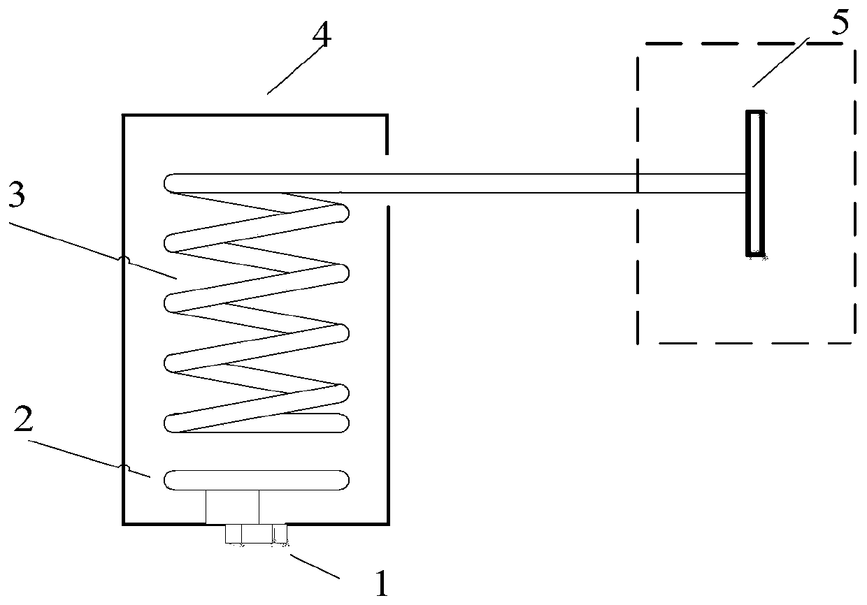
[0090] Such as figure 1 Shown is a schematic diagram of a high-frequency matching method for a MHz-level beam cutter provided by the present invention. The system is mainly composed of 1, 2, 3, 4, 5 and other components.

[0091] The power feed-in port 1 is used to feed the high-frequency signal provided by the power source into the spiral resonator through the coupling ring. The power feed-in port is placed on the bottom side of the square 4 of the shielded shell; Connect the power feed-in port to feed in power, and the other end is connected to one side of the square bottom side of the shielding shell; the center of the solenoid coil 3 starting end is 45-55 mm from the center of the coupling coil, and the starting end is connected to the shielding shell. The high-voltage side of the solenoid coil is connected to the cutting plate 5 through a coaxial feeder tube to provide a high-frequency voltage with a peak-to-peak value of 12KV and a frequency of 1-3MHz for the plate. Th...

Embodiment 2

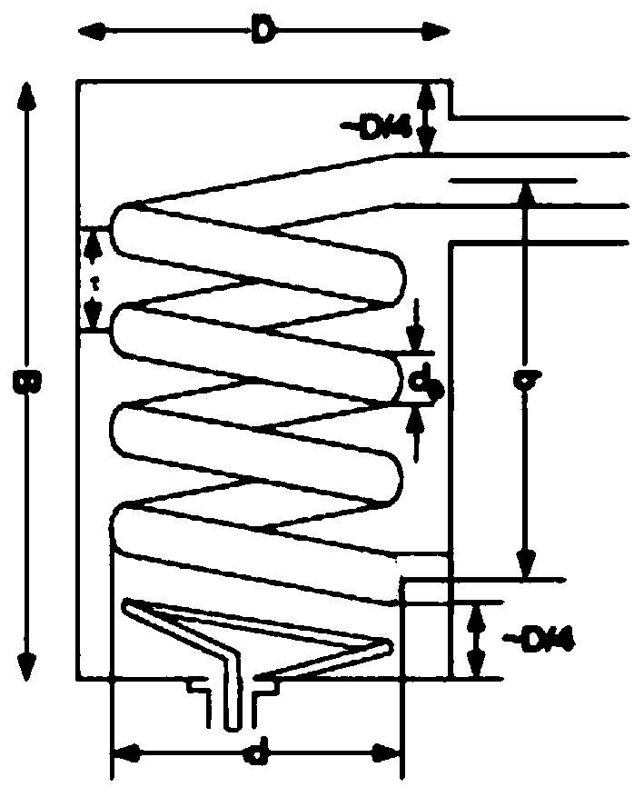
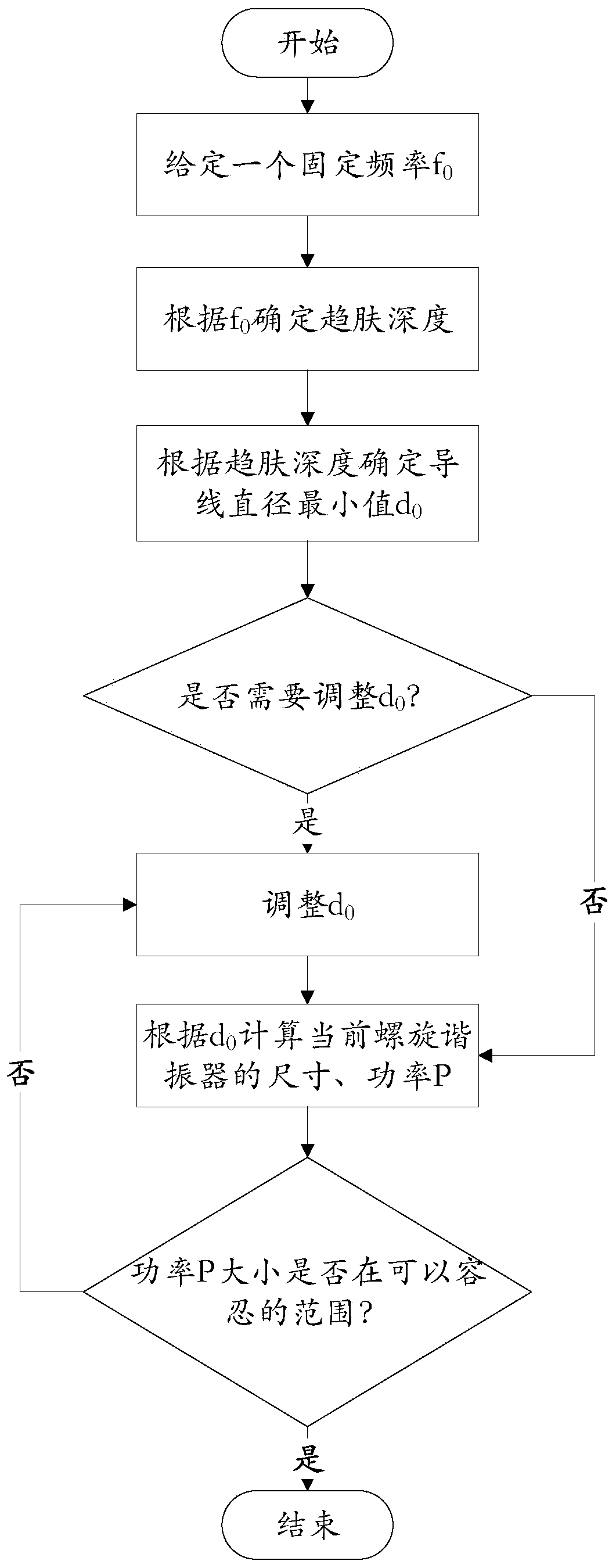
[0093] In this spiral resonator design scheme, first select copper wires (or copper tubes, but the wall thickness is greater than the skin depth) with a solenoid wire diameter of 3 to 12 mm, and then calculate the spiral resonance according to the size calculation formula at a fixed frequency The size of the resonator shell and the solenoid, and calculate the quality factor Q value, equivalent parallel resonance impedance, inductance value, etc., and finally calculate the theoretical power consumption and possible measured power consumption of the spiral resonator. According to experience, the actual power loss that may be measured Generally, it is about 2 times of the theoretical value. Since the theoretical power consumption is only an estimate, when there is a difference between the theoretical estimate and the actual measured power consumption, there is no need to adjust the power consumption, and the actual measured power consumption shall prevail.


PUM

PropertyMeasurementUnit
diameteraaaaaaaaaa
thicknessaaaaaaaaaa
diameteraaaaaaaaaa

Abstract

The invention discloses a high-frequency matching method for a MHz-level beam cutter. The method comprises the following steps: giving a fixed resonant frequency f0; determining tend skin depth according to the given resonant frequency f0; determining the minimum value d0 of the diameter of a wire according to the tend skin depth, wherein the d0 needs to consider two conditions that the size of ashielding housing is as small as possible and the power is in a bearable range; calculating the minimum size of the spiral resonator according to d0; calculating corresponding power P according to theminimum size of a spiral resonator; judging whether the power P is within the bearable range or not; if the power is not in the bearable range, adjusting the d0, and returning to the step 4; and if the power is in the bearable range, taking the size of the spiral resonator corresponding to the current d0 as the final size. By changing the shape of the spiral wire, changing the size of the spiralwire, changing the proportional relation between the spiral wire and the power P and changing the proportional relation between the number of turns N of a coil and the inductance L, an unexpected technical effect of reducing the size of the spiral resonator by 50% is achieved.

Description

technical field [0001] The invention belongs to the field of accelerator beam cutting, and in particular relates to a high-frequency matching method of a MHz-level beam cutter. Background technique [0002] High-frequency matching is the key link in the design of the beam cutter. The high-frequency sine wave voltage provided by the helical resonator acts on the particle beam to realize the lateral modulation of the beam. The beam drifts for a certain distance and then passes through the beam-limiting slit Finally, only a part of the particles can pass through the slit, and the other particles will be cut off, so as to realize the conversion from the direct current beam to the pulse beam and realize the pulse of the beam. [0003] As an alternative structure of general LC resonance, the helical resonator is composed of a helical inner conductor and a cylindrical shielding shell. The parameters of the helical resonator directly affect the frequency and pulse width of the cutti...

Claims


Application Information

Patent Timeline
Patent Type & Authority Patents(China)
IPC IPC(8): H05H7/18H05H7/12
CPCH05H7/12H05H7/18
Inventor 黄鹏李鹏展安世忠宋国芳侯世刚曹磊
Owner CHINA INSTITUTE OF ATOMIC ENERGY
Why Eureka
Try Eureka