Remote-controlled liquid embolism material precise injection device

An injection device and remote control technology, applied in the field of medical devices, can solve the problems of long duration of injection process, great human injury, whether to continue the injection or suspend the injection. The time of exposure to X-ray environment, the effect of reducing the difficulty of surgical operation and simplifying the operation process

Pending Publication Date: 2020-01-14
SHANGHAI CHANGHAI HOSPITAL
View PDF2 Cites 9 Cited by
  • Summary
  • Abstract
  • Description
  • Claims
  • Application Information

AI Technical Summary

Problems solved by technology

The prior art has the following disadvantages: when injecting liquid embolic materials, the doctor needs to perform the injection operation in the interventional catheterization room, the injection process lasts for a long time, and there is X-ray radiation in the interventional catheterization room, and medical personnel have to be exposed to X-rays for a long time, which is harmful to the human body. the damage is very large
When injecting liquid embolic material, it is necessary to decide whether to continue the injection or suspend the injection at any time according to the movement of the embolic material inside the deformity or the reflux situation. When the suspension is suspended, wait for a few seconds before injecting again. If the embolic material is not satisfactory, it is still suspended Inject, if satisfied, continue to inject until the course is not satisfactory; throughout the operation, this iterative process may be repeated hundreds of times
However, the existing micro-injection pump cannot be controlled remotely, and the injection cannot be repeatedly suspended at any time

Method used


Image

  • Remote-controlled liquid embolism material precise injection device
  • Remote-controlled liquid embolism material precise injection device
  • Remote-controlled liquid embolism material precise injection device

Examples


Embodiment 1

[0035] Example 1 Remotely Controllable Precision Injection Device for Liquid Embolism Material

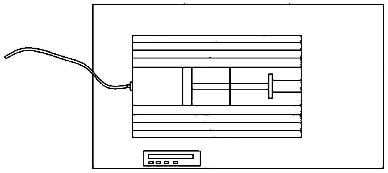
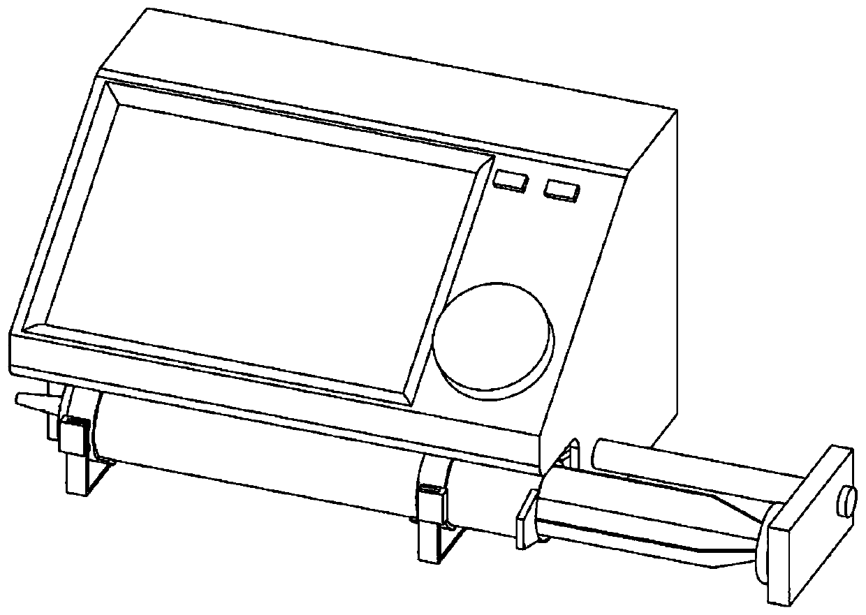
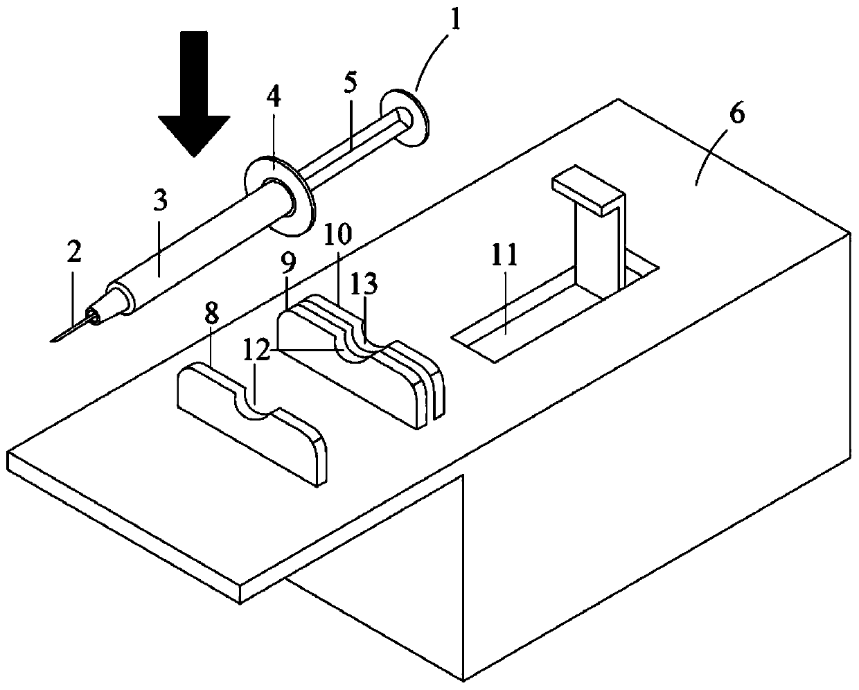
[0036] See Figure 3-Figure 6 . attached image 3 It is a schematic structural diagram of the remote-controllable liquid embolic material precision injection device of the present invention, with Figure 4 for image 3 The schematic diagram of the assembled syringe and injection workbench, attached Figure 5 It is a schematic diagram of the internal structure of the injection workbench, with Image 6 It is a schematic diagram of the structure of the remote switch controller.

[0037] A remote-controllable precision injection device for liquid embolism materials, which is used in conjunction with a syringe attached to liquid embolism material products. The structure of the syringe 1 includes a needle 2, a syringe 3, the outer edge of the tail of the syringe 4, and a syringe push rod 5. The injection device includes an injection workbench 6 for automatic injection of the syring...


PUM


Abstract

The present invention relates to the technical field of medical devices and particularly discloses a remote-controlled liquid embolism material precise injection device. The device comprises an injection workbench and a remote switch controller, and a support frame is arranged on a surface of the injection workbench; a main switch, a power supply, a wireless signal receiver, a remote switch, a motor, a lead screw, a lead screw nut and a lead screw nut seat are arranged in a box body of the injection workbench, a workbench push rod is fixedly arranged on an upper surface of the lead screw nut seat, and the push rod extends out of a push hole; and the remote switch controller comprises a switch controller body, a battery and a wireless signal transmitter, the battery is electrically connected with the wireless signal transmitter, and the wireless signal transmitter is connected with the wireless signal receiver through a wireless signal. The remote-controlled liquid embolism material precise injection device can accurately control injection dosage of a liquid embolism material in operation processes, and reduces time of exposing medical staff to an X-ray environment when the liquid embolism material is injected in interventional operations of cerebral arteriovenous malformation, etc. by utilizing wireless control.

Description

technical field [0001] The invention relates to the technical field of medical instruments, in particular to a remote-controllable precision injection device for liquid embolism material. Background technique [0002] Cerebral vascular malformations or multiple vascular diseases represented by cerebrovascular malformations are common clinical diseases and usually require interventional therapy. Interventional therapy is a treatment method in which medical personnel deliver embolic materials to the diseased site through various catheters under the guidance of X-rays to complete the blockage of diseased blood vessels. The specific method is: puncture the arterial sheath through the femoral artery, and in the case of a definite diagnosis by cerebral angiography, insert a catheter through the arterial sheath to the carotid artery, and then insert a microcatheter through the catheter, and deliver the tip of the microcatheter to the carotid artery. Within the arteries feeding the...

Claims


Application Information

Patent Timeline
Patent Type & Authority Applications(China)
IPC IPC(8): A61M5/20A61M5/31
CPCA61M5/008A61M5/20A61M5/31A61M2005/2006A61M2205/33
Inventor 刘建民李强方亦斌许奕李嘉楠尚成浩
Owner SHANGHAI CHANGHAI HOSPITAL
Why Eureka
Try Eureka