Energy-conservation and environmental-protection photovoltaic energy storage blind window

A photovoltaic energy storage, energy saving and environmental protection technology, applied in photovoltaic modules, photovoltaic power generation, photovoltaic module support structures, etc., can solve problems such as the inability to guarantee the stable installation of solar photovoltaic panels, the lack of purification structure for blinds, and the lack of environmental protection concepts, etc. Human body hazard, reducing gas failure, avoiding high temperature spontaneous combustion effect

Inactive Publication Date: 2020-01-14
合肥钉邻社区服务有限公司
View PDF8 Cites 0 Cited by
  • Summary
  • Abstract
  • Description
  • Claims
  • Application Information

AI Technical Summary

Problems solved by technology

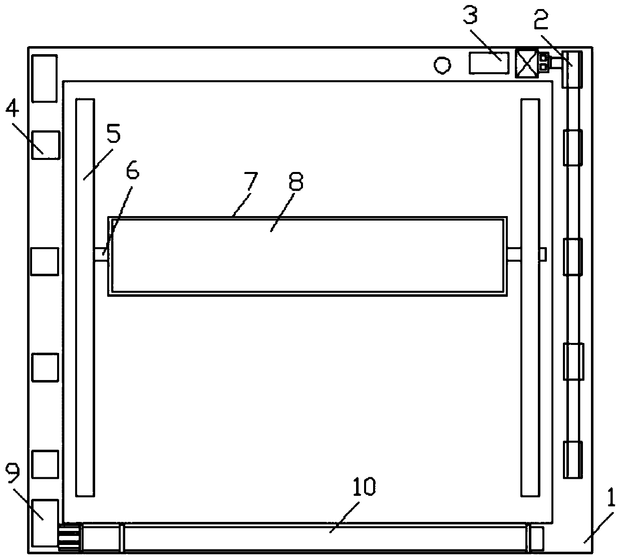
Electric control blinds are used as a carrier for new energy storage and utilization using solar energy, especially household photovoltaic energy storage shutters used in the background of family and office. At present, solar power generation technology has not been used reasonably. The electricity is not enough to save energy, and there is no specific shutter structure design for installing solar photovoltaic panels on the shutters, and the installation stability of solar photovoltaic panels cannot be guaranteed. With the serious air quality pollution in the current city, when the shutters are opened for ventilation, polluted gases are easy to enter Indoors are harmful to human health. For polluting gases, shutters currently lack a suitable purification structure, and the overall lack of environmental protection concepts. In order to solve the above problems, an energy-saving and environmentally friendly photovoltaic energy storage shutter is designed.

Method used


Image

  • Energy-conservation and environmental-protection photovoltaic energy storage blind window
  • Energy-conservation and environmental-protection photovoltaic energy storage blind window
  • Energy-conservation and environmental-protection photovoltaic energy storage blind window

Examples


Embodiment Construction

[0023] The following will clearly and completely describe the technical solutions in the embodiments of the present invention with reference to the accompanying drawings in the embodiments of the present invention. Obviously, the described embodiments are only some, not all, embodiments of the present invention. Based on the embodiments of the present invention, all other embodiments obtained by persons of ordinary skill in the art without making creative efforts belong to the protection scope of the present invention.

[0024] In the description of the present invention, it should be noted that the orientation or positional relationship indicated by the terms "vertical", "upper", "lower", "horizontal" etc. is based on the orientation or positional relationship shown in the drawings, and is only In order to facilitate the description of the present invention and simplify the description, it does not indicate or imply that the device or element referred to must have a specific o...


PUM


Abstract

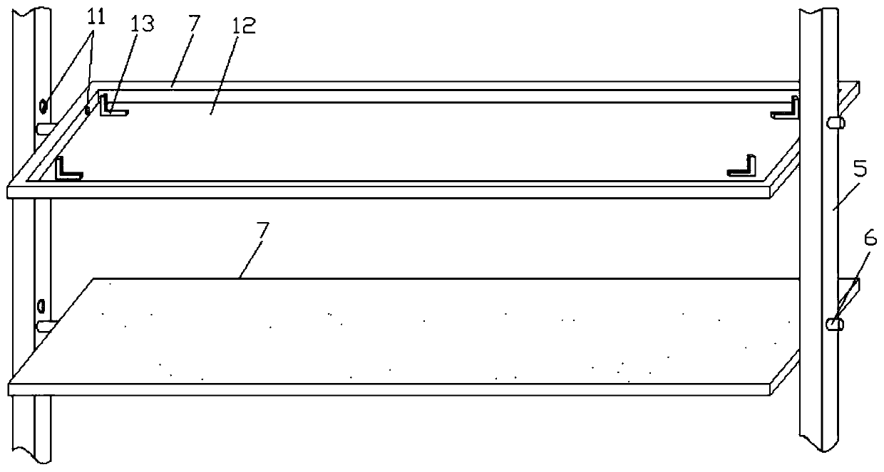
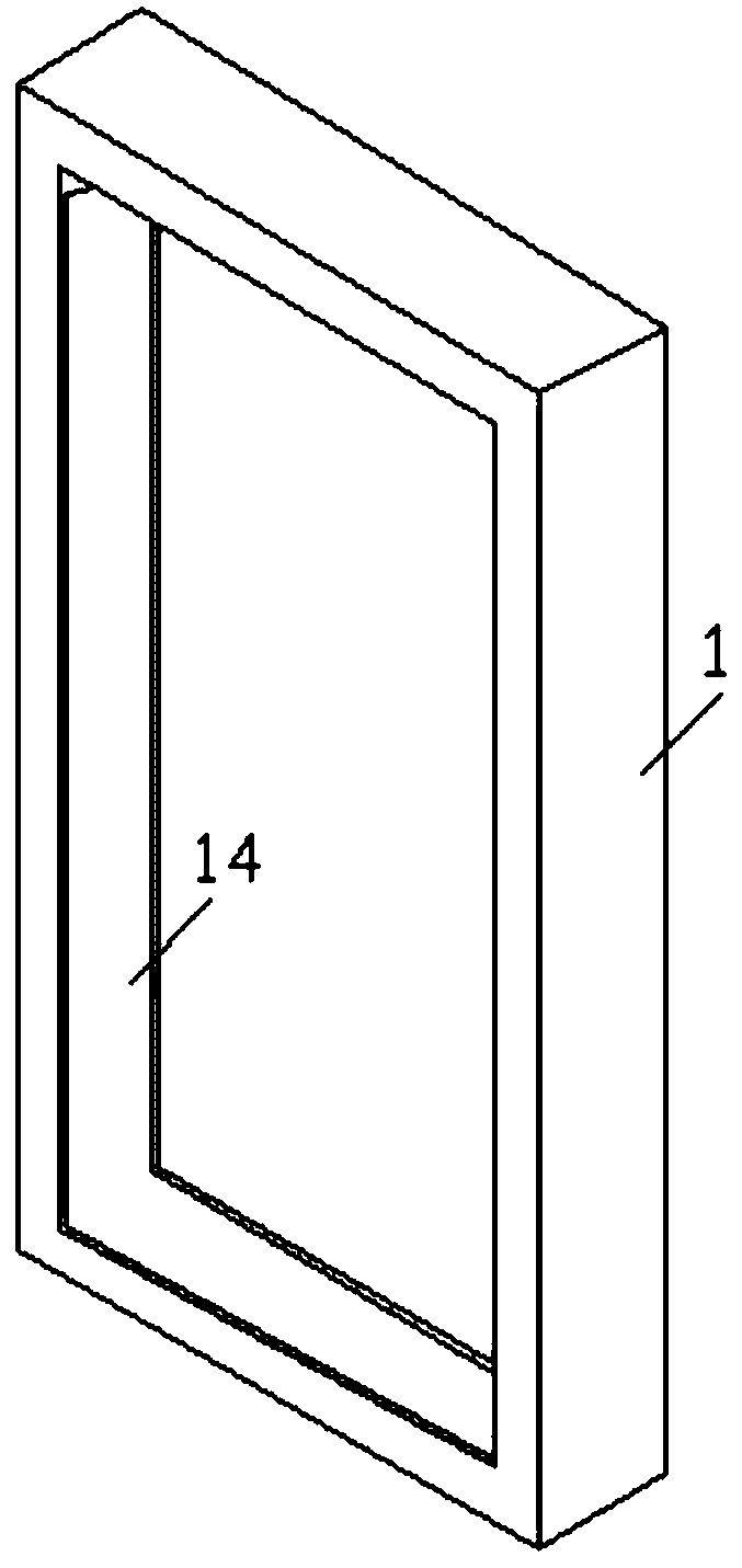
The invention discloses an energy-conservation and environmental-protection photovoltaic energy storage blind window. The blind window comprises a mounting frame, louver blades, a heat dissipating module and activated carbon filter screen frames; multiple louver blades are arranged in a middle cavity of the mounting frame; the two ends of each louver blade are rotationally connected with support rods through rotating rods; accommodating cavities are concavely formed in the four edges of the mounting frame; the support rods of the louver blades are arranged in the accommodating cavities on theleft and right sides of the mounting frame; multiple charging and discharging controllers are arranged in the accommodating cavity on the left side of the mounting frame at intervals; L-shaped brackets are arranged at the four angles of the accommodating grooves of the louver blades; solar photovoltaic panels are connected to the tops of the L-shaped brackets; wiring boxes of all the solar photovoltaic panels are connected with the charging and discharging controllers in symmetric positions through photoelectric connectors; the charging and discharging controllers are connected with accumulators; the activated carbon filter screen frames are arranged on one sides of the inner surfaces of the louver blades; and through arrangement of the activated carbon filer screen frames, gas entering indoors after opening or closing of the louver blades is conveniently filtered and purified, the gas is reduced, the harm to human bodies is reduced, and higher environmental protectiveness is achieved.

Description

technical field [0001] The invention relates to the related technical field of furniture doors and windows, in particular to an energy-saving and environment-friendly photovoltaic energy storage shutter. Background technique [0002] Shutters are a style of windows that originated in China. Blinds are developing very rapidly in China, because ordinary windows cannot play the role of sunshade and ventilation. By controlling the opening and closing angle of the shutters, people can obtain more ideal light and ventilation effects. The shutters currently on the market are mainly The opening and closing and opening and closing angle of the shutters are controlled by mechanical hinges, some are manually controlled, and some are controlled by motor drive. Environmental protection is becoming more and more important today, and clean energy has a huge market and potential. Solar energy, as the most direct source of energy for human beings, has become the first choice for clean ener...

Claims


Application Information

Patent Timeline
IPC IPC(8): E06B7/086E05F15/71E05F15/611H02J7/35H02S20/32H02M7/42H02K7/14H01M10/613H01M10/6554H01M10/6567H05K7/20
CPCE06B7/086E05F15/611E05F15/71H02J7/35H02K7/14H02M7/42H05K7/20218H05K7/2039H02S20/32H01M10/613H01M10/6554H01M10/6567Y02B10/10Y02E10/56Y02E60/10
Inventor 蒋克项
Owner 合肥钉邻社区服务有限公司
Why Eureka
Try Eureka