
Magnetic iron ore beneficiation method

A beneficiation method and magnetite technology, applied in chemical instruments and methods, wet separation, solid separation, etc., can solve the problems of high impurity and iron content, high water content and high powder content, and achieve improved metal recovery rate, short process, The effect of improving the efficiency of crushing operations

Active Publication Date: 2020-01-17
MASTEEL GRP MINING CO LTD
View PDF9 Cites 9 Cited by
  • Summary
  • Abstract
  • Description
  • Claims
  • Application Information

AI Technical Summary

Problems solved by technology

[0004] The purpose of the patent of the present invention is to shorten the existing magnetite beneficiation process through a new beneficiation process, better solve the problems of high impurity and iron content in the ore, high water content and powder content, improve operating efficiency, and reduce grinding energy consumption. Improve the grinding and separation effect and process stability, thereby improving the quality of the final concentrate product

Method used


Image

  • Magnetic iron ore beneficiation method
  • Magnetic iron ore beneficiation method
  • Magnetic iron ore beneficiation method

Examples


Embodiment 1

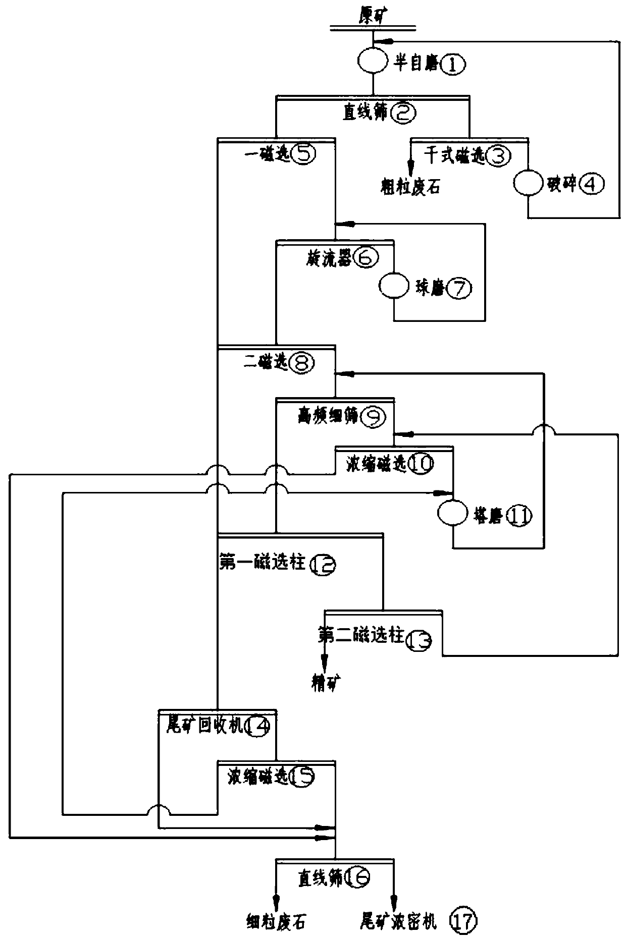
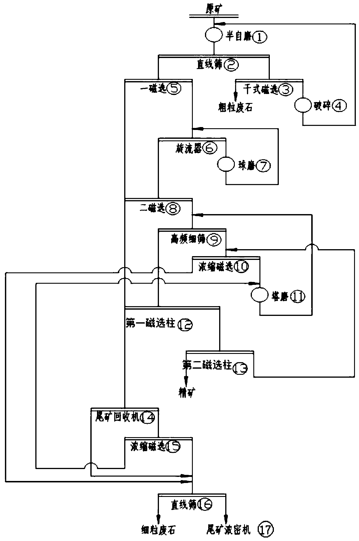
[0034] Such as figure 1 As shown, a beneficiation method of magnetite, the steps are:

[0035] A. The ore with a particle size of 0-350mm and a grade of 25%-35% is conveyed by a semi-automatic mill 1 by the ore-collecting belt, self-grinding to a particle size of -60mm;

[0036] B. The first-stage semi-automatic mill discharge adopts linear sieve 2 for screening, and the products on the linear sieve 2 (-60mm—+3mm) are discarded by weak magnetic dry separator 3. The tailings are used as building materials and dry magnetic The concentrate enters the stone crusher 4 for crushing, and the crushed product returns to the semi-automatic mill 1 for re-grinding;

[0037] C. The product under the linear sieve 2 (-3mm) enters the first stage wet magnetic separator 5 for separation, the magnetic field strength is 350-400mT, and the first stage magnetic concentrate grade is 45%-52%;

[0038] D. The magnetic concentrate of the first stage is transported by a slurry pump to the hydrocyclone 6 for cl...

Embodiment 2

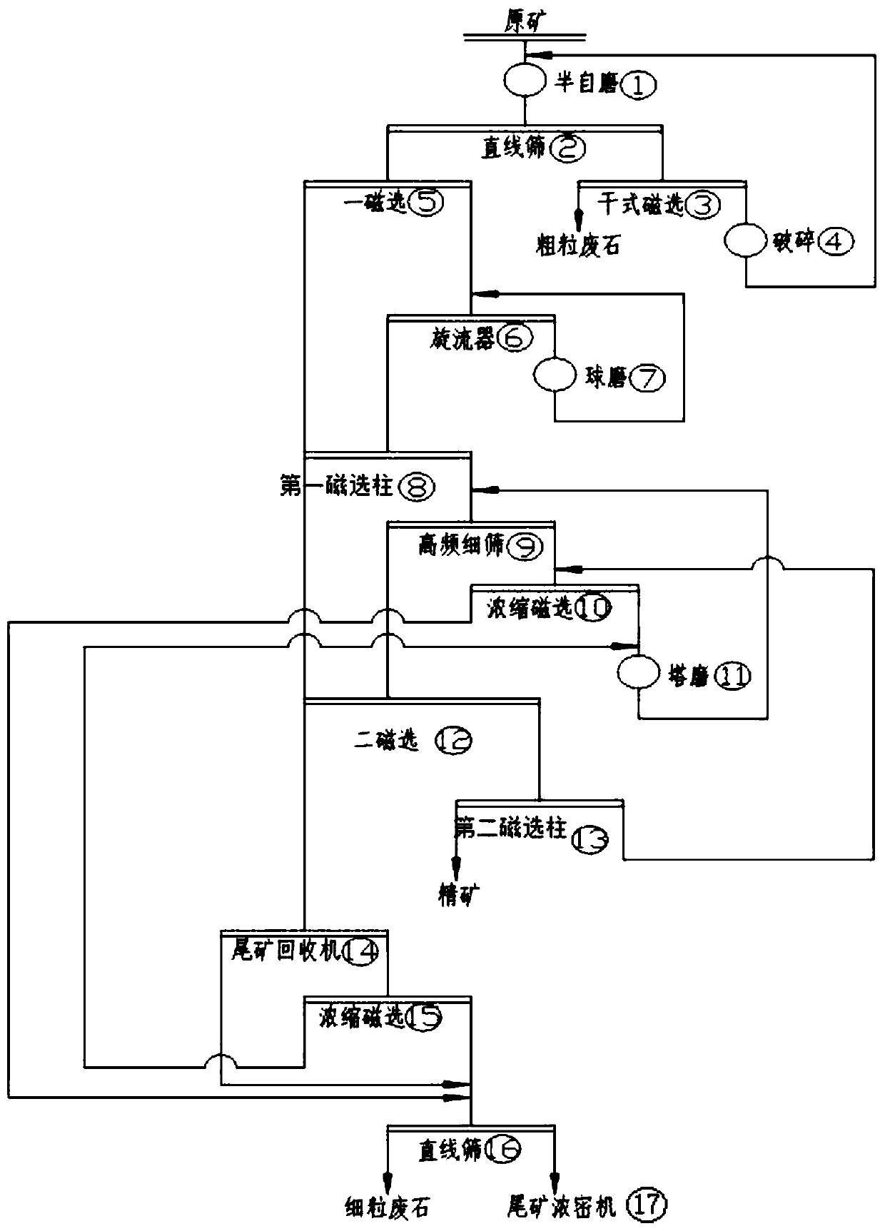
[0047] Such as figure 2 As shown, the two-stage weak magnetic separator and the first magnetic separation column in the first scheme are interchanged. The first magnetic separation column not only provides the purpose of beneficiation, but also plays a role in desilting the concentrate. After the ore is pre-desludged, it can improve the operation efficiency of the subsequent 9 high-frequency fine screens and reduce the sludge content of the concentrate. After the second stage of weak magnetic separator magnetic separation, it can reduce the inclusion of the concentrate and improve the grade of the concentrate.

[0048] A method for beneficiating magnetite, the steps are:

[0049] A. The ore with a particle size of 0-350mm and a grade of 25%-35% is conveyed by a semi-automatic mill 1 by the ore-collecting belt, self-grinding to a particle size of -60mm;

[0050] B. One-stage semi-automatic mill discharge (-60mm) adopts linear sieve 2 for sieving, linear sieve 2 (-60mm—+3mm) products...


PUM

PropertyMeasurementUnit
particle diameteraaaaaaaaaa
strengthaaaaaaaaaa

Abstract

The invention discloses a magnetic iron ore beneficiation method which comprises the steps of utilizing a semi-autogenous grinding or autogenous grinding mill for replacing crushing operation with a long flow, so that the crushing operation efficiency is improved, meanwhile, the failure rate of the crushing operation is reduced, and advanced waste abandoning can be realized; adopting a two-stage ore grinding process comprising ball milling and tower milling for grinding and separating operation, so that the ore grinding efficiency is improved; adopting two-stage low intensity magnetic separation, high-frequency fine screening, a first magnetic separation column and a second magnetic separation column for separation operation, so that a separation index is improved; scavenging, recovering and concentrating stage tailings, and returning to ore grinding and recleaning, so that the metal recovery rate is improved; and grading primary and secondary magnetic tailings through a linear screenso as to obtain building materials for sale. According to the ore beneficiation method provided by the invention, the process flow is shortened, meanwhile, the process stability and the separation precision are greatly improved, and the production efficiency is improved.

Description

Technical field [0001] The invention belongs to the technical field of beneficiation and relates to a magnetite beneficiation method with a short beneficiation process. Background technique [0002] Most of the domestic magnetite beneficiation adopts the two, three or four-stage closed-circuit crushing and the process flow of stage grinding stage separation. After the high-pressure roller mill is promoted and applied in metallurgical mines, the crushing efficiency and grinding efficiency are improved, but it also Make the crushing process longer and complicated. However, in many underground mines, because ①the raw ore contains a lot of iron and iron, the iron remover cannot be effectively solved, and the equipment is easily damaged; ②the water and powder content is high, and it is easy to block the mine bin and hopper. These problems have a greater impact on the efficiency of the crushing and grinding process of the long process. [0003] Cylinder magnetic separator is not high i...

Claims


Application Information

Patent Timeline
Patent Type & Authority Applications(China)
IPC IPC(8): B03B7/00
CPCB03B7/00
Inventor 王荣林张伟李明军王欢梁朝杰钱世湖杨松付
Owner MASTEEL GRP MINING CO LTD
Learn More