Graphite bipolar plate compression moulding forming system

A compression molding, bipolar plate technology, applied in the direction of presses, dust removal, cleaning methods and appliances, etc., can solve the problems of affecting surface hydrophilicity and hydrophobicity, affecting the next process, and damage to the plate sealing area, so as to improve labor production efficiency , Improve the product quality rate and ensure the effect of production accuracy

Active Publication Date: 2020-01-17
魔方氢能源科技(江苏)有限公司
View PDF5 Cites 9 Cited by
  • Summary
  • Abstract
  • Description
  • Claims
  • Application Information

AI Technical Summary

Problems solved by technology

However, due to the softness of the flexible graphite plate, a micro-vacuum state is formed after molding, and it is adsorbed on the surface of the mold. It is necessary to manually remove the waste edge and take the formed plate out of the mold.
After taking out the plate, it is necessary to manually remove the public channel and the waste of reducing agent and oxidizing agent inlet distribution inlet, which may easily cause damage to the sealing area of ​​the plate and waste material leakage. It will fail to pass the leak test and affect the next process.
The plate consistency and quality stability depend on the operator, and the plate is easily polluted by organic matter, which affects the hydrophilicity and hydrophobicity of the surface

Method used


Image

  • Graphite bipolar plate compression moulding forming system
  • Graphite bipolar plate compression moulding forming system
  • Graphite bipolar plate compression moulding forming system

Examples


Embodiment Construction

[0064] The following are specific embodiments of the present invention and in conjunction with the accompanying drawings, the technical solutions of the present invention are further described, but the present invention is not limited to these embodiments.

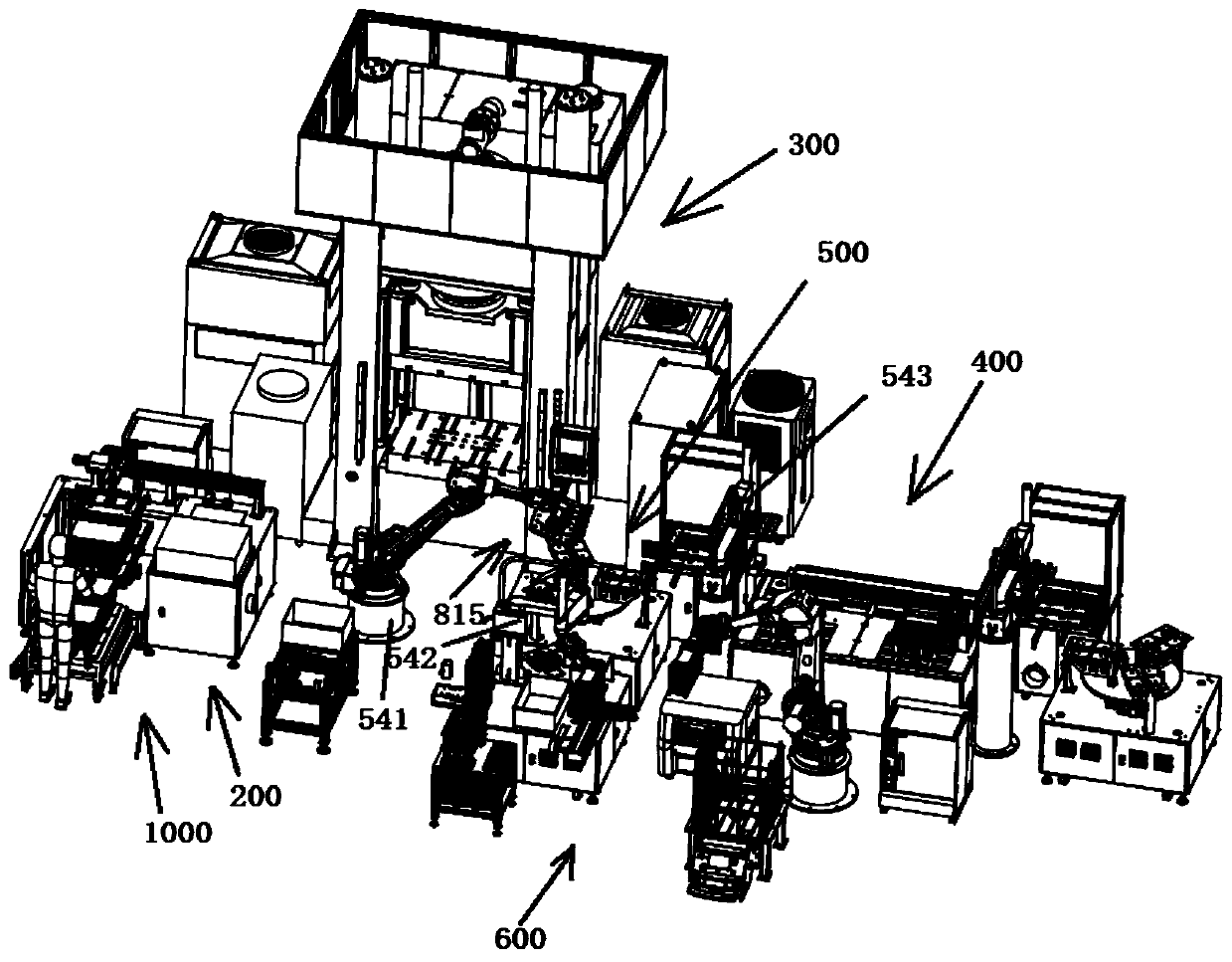
[0065] Such as figure 1 As shown, a graphite bipolar plate molding system invented includes: a feeding device 100, a cleaning device 200, a molding device 300, a conveying device 400, a deburring device 500, an automatic cage loading device 600 and an electric control system;

[0066] The feeding device 100 is used to feed the graphite plate onto the cleaning device;

[0067] Cleaning device 200, used to clean impurities on the surface of the graphite plate;

[0068] The molding device 300 is used to mold the cleaned graphite plate into a single bipolar plate;

[0069] The deburring device 500 is used for cutting the burrs around the single plate of the bipolar plate;

[0070] The conveying device 400 is used to transfe...


PUM


Abstract

The invention discloses a graphite bipolar plate compression moulding forming system. The graphite bipolar plate compression moulding forming system comprises a loading device, a sweeping device, a mould pressing device, a deburring device, a conveying device, an automatic cage loading device and an electric control system. The loading device is used for loading a graphite plate to the sweeping device, the sweeping device is used for sweeping impurities on the surface of the graphite plate, the mould pressing device is used for carrying out mould pressing on the cleaned graphite plate to forma bipolar plate single board, the deburring device is used for cutting burrs on the periphery of the bipolar plate single board, the conveying device is used for transferring a graphite plate to the mould pressing device from the sweeping device, after mould pressing is finished, wastes are transferred to the recycling position, the finished bipolar plate single board is transferred to the deburring device, after the deburring procedure is finished, the bipolar plate single board is transferred to the automatic cage loading device, the automatic cage loading device transfers the bipolar platesingle board to other stations, and the electric control system is electrically connected with the loading device, the sweeping device, the mould pressing device, the deburring device, the conveying device and the automatic cage loading device and used for controlling the devices. The system effectively ensures production precision in the bipolar plate mould pressing forming process, the product yield is improved, and the bipolar plate production cost is reduced.

Description

technical field [0001] The invention relates to the technical field of graphite bipolar plate preparation, in particular to a graphite bipolar plate compression molding system. Background technique [0002] The fuel cell bipolar plate is one of the important components of the fuel cell. It has the following functions and properties: separate fuel and oxidant, prevent gas from passing through; collect and conduct current, with high conductivity; designed and processed flow channels can transfer gas Evenly distributed to the reaction layer of the electrode for electrode reaction; can discharge heat and keep the battery temperature field uniform; corrosion resistance; shock and vibration resistance. Under the premise of maintaining a certain mechanical strength and a good gas barrier effect, the thickness of the bipolar plate should be as thin as possible to reduce the conduction resistance to current and heat. [0003] At present, bipolar plate materials can be roughly divide...

Claims


Application Information

Patent Timeline
Patent Type & Authority Applications(China)
IPC IPC(8): B30B9/28B30B15/00B30B15/30B30B15/08B08B5/02B08B15/00B08B15/02B08B13/00B65B35/16B65G47/74B23K26/38B23K26/08B23K26/70
CPCB30B9/28B30B15/0082B30B15/30B30B15/08B08B5/023B08B15/007B08B15/02B08B13/00B65B35/16B65G47/74B23K26/38B23K26/0884B23K26/702B23K2103/50Y02E60/50
Inventor 华周发胡强姚青
Owner 魔方氢能源科技(江苏)有限公司
Why Eureka
Try Eureka