
Method for reducing surface pollution generated when ion beams polish optical element

A technology for optical components and surface contamination, applied in optical surface grinders, grinding/polishing equipment, grinders, etc., can solve the problems of reduced transmittance, optical component pollution, black impurities, etc., to reduce impurity elements and improve processing. Quality, effect of improving cleanliness

Active Publication Date: 2020-01-21
CHINA WEAPON SCI ACADEMY NINGBO BRANCH
View PDF18 Cites 4 Cited by
  • Summary
  • Abstract
  • Description
  • Claims
  • Application Information

AI Technical Summary

Problems solved by technology

However, when ion beam polishing is used to etch and polish optical components, there will be certain pollution on the surface of optical components, and sometimes there will be black impurities. After polishing, due to the existence of impurities, its optical performance is mainly reduced in transmittance. , which seriously affects the later use

Method used


Image

  • Method for reducing surface pollution generated when ion beams polish optical element
  • Method for reducing surface pollution generated when ion beams polish optical element
  • Method for reducing surface pollution generated when ion beams polish optical element

Examples


Embodiment Construction

[0026] The specific implementation manners of the present invention will be further described in detail below in conjunction with the accompanying drawings and embodiments.

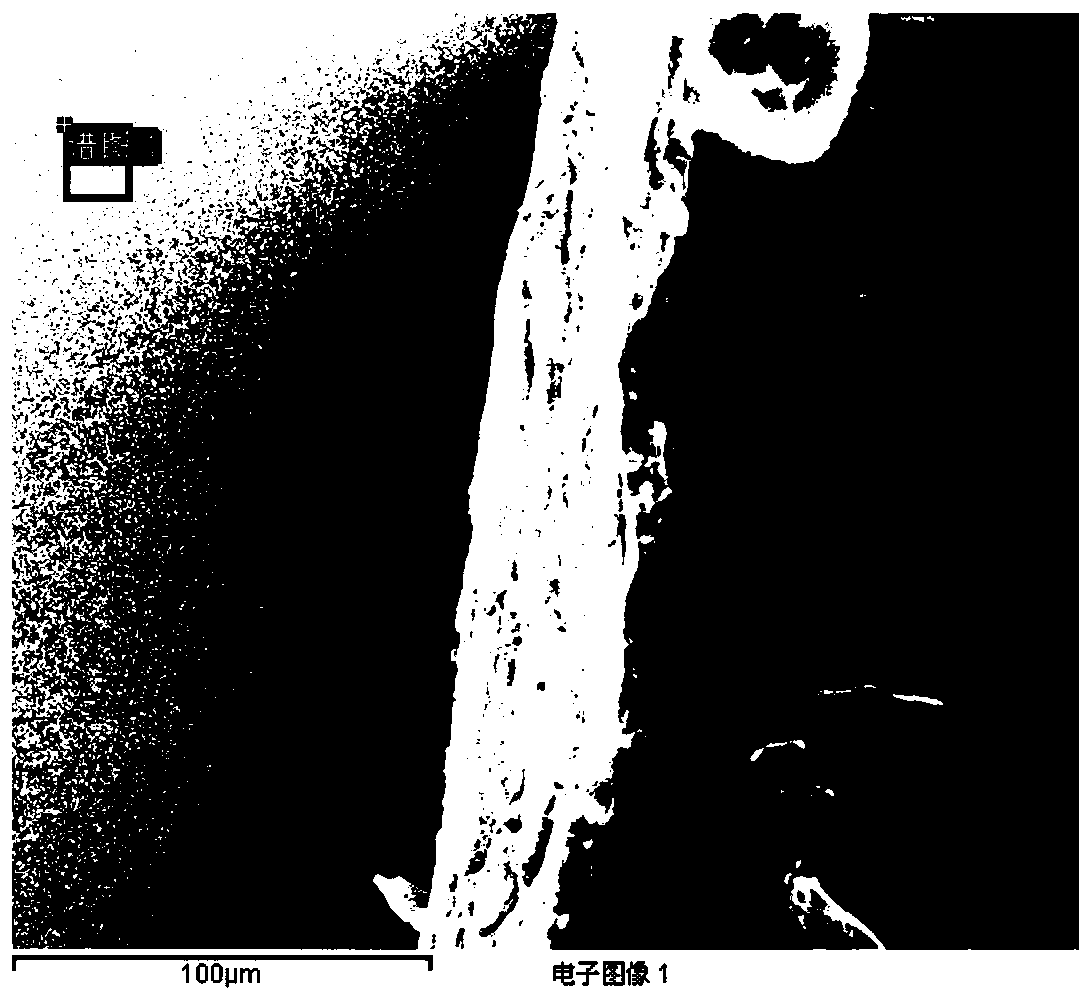
[0027] Such as Figure 1 to Figure 3 As shown, in the embodiment of the present invention, the optical element is placed in the ion beam polishing equipment and the optical element is subjected to ion beam polishing, the optical element after ion beam polishing is taken out from the vacuum chamber, and the sample with black impurities on the surface after contamination figure 1 shown.

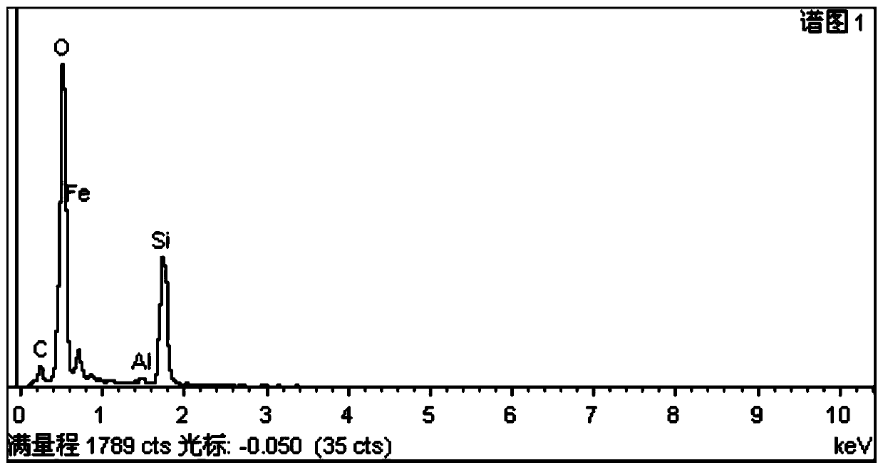
[0028] The X-ray diffractometer (XRD) analysis method is used to detect and analyze the black impurity area on the surface of the optical element polished by the ion beam polishing equipment, so as to determine the source of the impurity element; figure 2 It is the microscopic surface of optical components, and its composition is as follows image 3 As shown, according to the analysis of the curve measured by XRD, it ca...


PUM

PropertyMeasurementUnit
thicknessaaaaaaaaaa
thicknessaaaaaaaaaa
thicknessaaaaaaaaaa

Abstract

The invention relates to a method for reducing the surface pollution generated when ion beams polish an optical element. The method comprises the steps that 1), high-temperature adhesive tape is usedfor carrying out sealing treatment on the outer side of a clamp used for clamping the optical element in ion beam polishing equipment; 2), after the optical element is mounted on the clamp, the surfaces of the optical element and the clamp are cleaned, then the optical element and the clamp are placed in a secondary chamber of the ion beam polishing equipment, and finally the optical element is sent to a main chamber of the ion beam polishing equipment; 3), an ion source is mounted, and a grid network of the ion source adopts a grid network with the sputtering rate being lower than the metal silver sputtering rate; and 4), the ion beam polishing equipment is started, the ion source is started, an ion beam current emitted by the ion source is measured by using the Faraday cup, and after theion source runs for a certain set time t, the optical element is subjected to ion beam polishing. By adopting the method, the surface of the optical element after ion beam processing is clean, the pollution is effectively inhibited, and the processing quality is improved.

Description

technical field [0001] The invention relates to the technical field of precision manufacturing, in particular to a method for reducing contamination on the surface of an ion beam polishing optical element. Background technique [0002] Ion beam polishing is usually used for the final processing of ultra-precision optical components. It is a polishing technology with removal accuracy reaching the atomic level. It is considered to be the optical component modification technology with the highest processing accuracy and good modification effect. [0003] In the process of ion beam polishing, the ion beam with a certain energy and spatial distribution bombards the surface of the optical element, and the physical sputtering effect that occurs during the bombardment is used to remove the surface material of the optical element to achieve the purpose of correcting the surface shape error, and the processing accuracy reaches nanometers. class. The material removal mechanism of ion ...

Claims


Application Information

Patent Timeline
Patent Type & Authority Applications(China)
IPC IPC(8): B24B13/00B24B1/00
CPCB24B1/00B24B13/00
Inventor 王大森李晓静聂凤明裴宁郭海林张旭
Owner CHINA WEAPON SCI ACADEMY NINGBO BRANCH
Learn More