Supercharge Your Innovation With Domain-Expert AI Agents!

Magnetorheological sub-aperture polishing device suitable for large-caliber optical elements

A magnetorheological polishing and polishing device technology, which is applied in the direction of optical surface grinders, grinding drive devices, grinding/polishing equipment, etc., can solve the problems of low manufacturing efficiency of optical components, increase the efficiency of magnetorheological polishing, improve Improve processing efficiency and improve the effect of effective processing area

Active Publication Date: 2020-01-24
INST OF OPTICS & ELECTRONICS - CHINESE ACAD OF SCI
View PDF10 Cites 0 Cited by
  • Summary
  • Abstract
  • Description
  • Claims
  • Application Information

AI Technical Summary

Problems solved by technology

[0003] The purpose of the present invention is to solve the problem of low manufacturing efficiency of large-diameter low-damage optical elements used in the field of strong lasers, and propose a magnetorheological sub-aperture polishing device based on permanent magnets

Method used


Image

  • Magnetorheological sub-aperture polishing device suitable for large-caliber optical elements
  • Magnetorheological sub-aperture polishing device suitable for large-caliber optical elements
  • Magnetorheological sub-aperture polishing device suitable for large-caliber optical elements

Examples


specific Embodiment approach 1

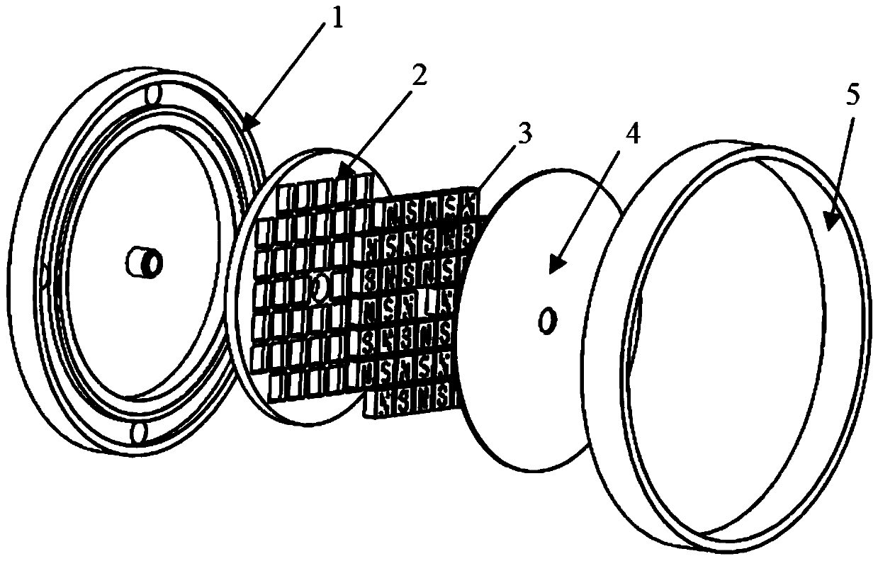
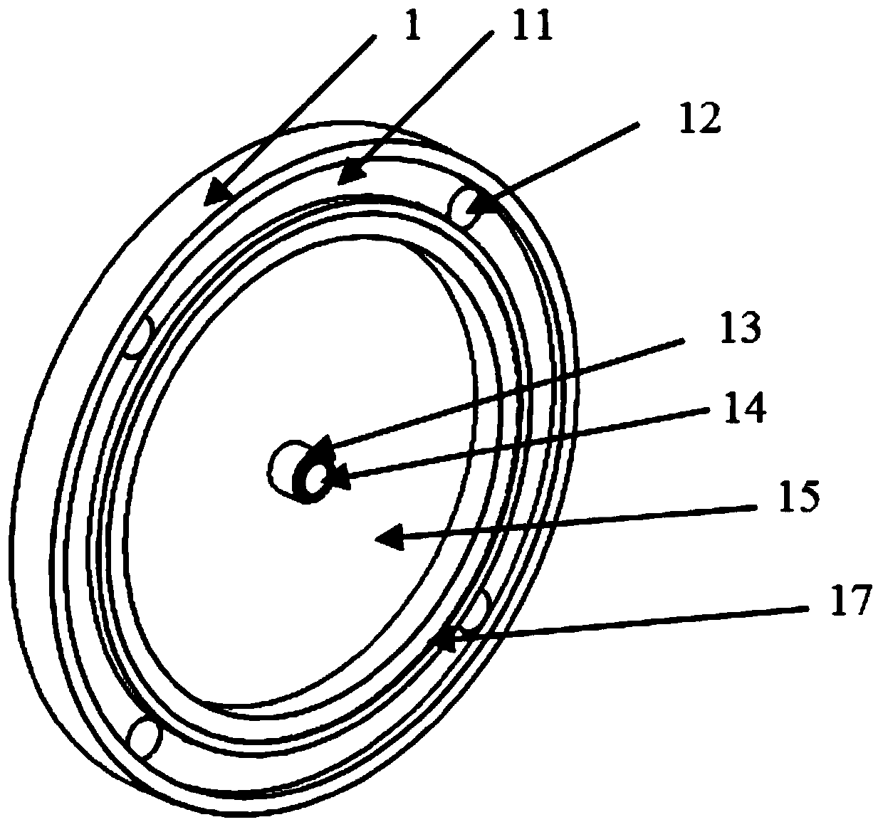
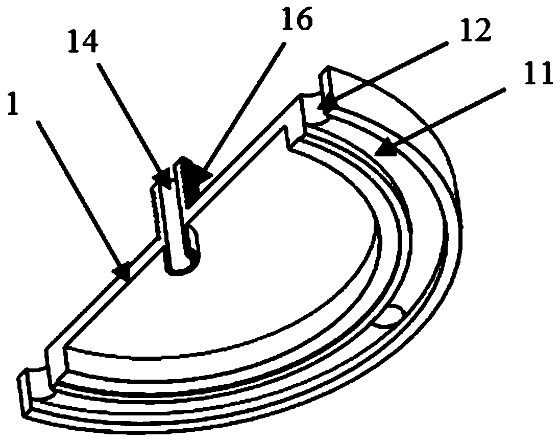
[0029] Specific implementation mode 1: This implementation mode is mainly aimed at flat-plate optical components and optical components with small curvature. Figure 1 to Figure 8 To illustrate this embodiment, as shown in 4, the pure iron back plate 2 is a flat plate, which is embedded into the figure 1 In the annular groove 15 of the main body 1 of the magnetorheological sub-aperture polishing device shown.

[0030] The permanent magnets in the permanent magnet array 3 are embedded in the grooves of the pure iron back plate 2 in a cross arrangement of N poles 31 and S poles 32 , and the magnetic lines of adjacent permanent magnets in the array are closed to form a magnetic field for processing. There is no permanent magnet arrangement at the center 33 of the permanent magnet array, and the permanent magnet can be adsorbed on the pure iron back plate 2 under the action of magnetic force. The groove depth of the pure iron back plate 2 is less than 20% of the thickness of the ...

specific Embodiment approach 2

[0035] Embodiment 2: Embodiment 2 is mainly aimed at large curvature and high steepness optical elements, combined with Embodiment 1 and Figure 9 Describe the second embodiment, the device assembly and use method of the second embodiment is the same as the first embodiment, the difference is that the pure iron back plate 2, the permanent magnet array 3 and the isolation plate 4 need to be changed to have a certain curvature, and the curvature is the same as Pure iron back plate-2-1, permanent magnet array-3-1 and isolation plate-4-1 whose curvature matches the workpiece to be processed.


PUM

PropertyMeasurementUnit
thicknessaaaaaaaaaa

Abstract

The invention discloses a permanent magnet sub-aperture polishing device suitable for large-caliber optical elements, and relates to the technical field of high-precision optical element efficient machining. The device comprises a agnetorheological sub-aperture polishing device main body, a pure iron back plate, a permanent magnet array, an isolation plate and a soft rubber ring. magnetorheological polishing liquid enters a device machining device from a center through hole, is dispersed to the machining area under dual effects of conveying pressure and device rotation centrifugal force, and is recovered on the device edge after passing through a permanent magnet machining area. The magnetorheological polishing liquid achieves a certain fluidity to adapt to the curvature change of curved surfaces for machining of large-curvature and high-steepness optical elements. The permanent magnet number and size in the permanent magnet array can be reduced or increased according to machined element size demands, so that the contact area of the magnetorheological polishing liquid and the optical elements is effectively increased, and the material removing efficiency and the high-precision shape correcting efficiency of large-caliber and curvature optical elements can be prominently improved.

Description

technical field [0001] The invention relates to the technical field of efficient processing of high-precision optical elements, in particular to a magnetorheological sub-aperture polishing device suitable for large-diameter optical elements. Background technique [0002] With the development of high-power laser optics technology, the size of optical components used in high-power laser optical systems is getting larger and larger. against photodamage threshold. Magneto-rheological polishing technology is an effective means to reduce the surface and sub-surface damage of optical components. Magnetorheological polishing technology uses the magnetorheological fluid ribbon on the polishing wheel to sweep the optical surface, so as to realize the material removal of optical components. This technology has extremely high certainty, and the processing convergence rate is very high. However, due to the small contact area between the magnetorheological fluid ribbon and the surface of...

Claims


Application Information

Patent Timeline
Patent Type & Authority Applications(China)
IPC IPC(8): B24B13/00B24B1/00B24B41/04B24B47/12B24B57/02
CPCB24B1/005B24B13/00B24B41/04B24B47/12B24B57/02
Inventor 辛强刘海涛万勇建
Owner INST OF OPTICS & ELECTRONICS - CHINESE ACAD OF SCI
Features
  • R&D
  • Intellectual Property
  • Life Sciences
  • Materials
  • Tech Scout
  • Unparalleled Data Quality
  • Higher Quality Content
  • 60% Fewer Hallucinations
Learn More