
Conductive slip ring for lightning protection

A conductive slip ring and lightning protection technology, which is applied in the direction of circuits, current collectors, electrical components, etc., can solve the problems of inability to realize lightning protection for rotating equipment, low instantaneous large current carrying capacity, and low contact reliability, and achieve lightning protection ability, realize the lightning protection function, and the effect of reasonable structural design

Pending Publication Date: 2020-01-31
JIUJIANG JINGDA MEASUREMENT TECH
View PDF0 Cites 1 Cited by
  • Summary
  • Abstract
  • Description
  • Claims
  • Application Information

AI Technical Summary

Problems solved by technology

Ordinary conductive slip rings use brush wires to make line contact with the rotor, and the contacts are mostly made of cheap metal materials such as brass and silver alloys. The low problem, in the natural environment of lightning current interference, hit the process, the voltage drop generated by the ordinary conductive slip ring is high, the heat is serious, so the contact of the brush wire is easy to be broken down, burnt and lead to conductive slip ring Damage, so that the conductive slip ring cannot perform lightning current shunting and drainage on the radar system turret that rotates with the rotor of the ordinary conductive slip ring, so lightning protection for rotating equipment (such as the radar system turret) cannot be realized

Method used


Image

  • Conductive slip ring for lightning protection
  • Conductive slip ring for lightning protection
  • Conductive slip ring for lightning protection

Examples


Embodiment Construction

[0022] The present invention will be described in further detail below in conjunction with the embodiments and with reference to the accompanying drawings.

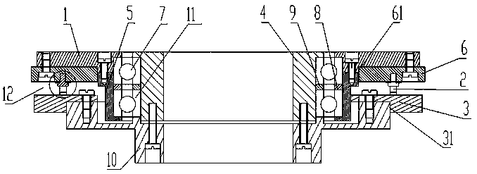
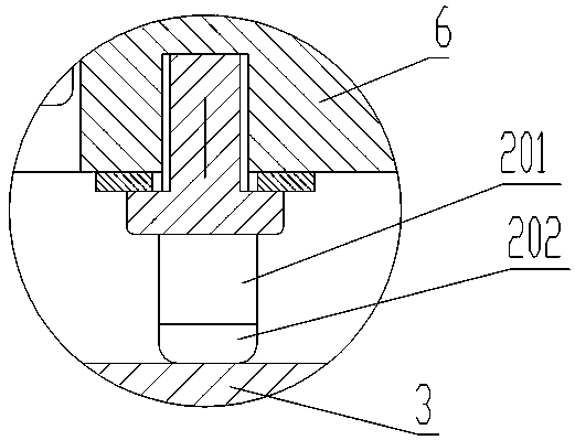
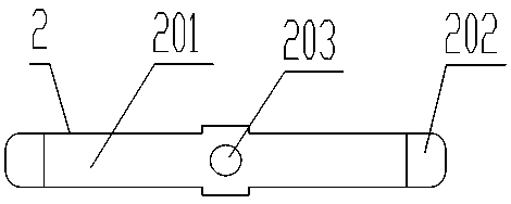
[0023] A conductive slip ring for lightning protection, comprising a fixed plate 6, a moving plate 3, a stator connecting plate 1, a bearing seat 5, a central shaft 4, a rotor connecting plate 10, a reed set 2, an upper bearing 7 and a lower bearing 11, in The bottom of the ring-shaped stator connecting plate 1 is provided with a fixed plate step groove 61, through the cooperation and positioning of the fixed plate step groove 61, the screw fixes the ring-shaped fixed plate 6 on the bottom of the stator connecting plate 1; The step groove 31 of the moving disk, through the cooperative positioning of the step groove 31 of the moving disk, the screw fixes the moving disk 3 on the top of the ring-shaped rotor connecting disk 10; the fixed disk 1 is opposite to the moving disk 3 and there is a gap 12; the ring-shaped central a...


PUM


Abstract

The invention discloses a conductive slip ring for lightning protection. The conductive slip ring comprises a fixed plate, a moving plate, a stator connecting plate, a bearing base, a central shaft,a rotor connecting plate, a reed group, an upper bearing and a lower bearing. The fixed plate, the stator connecting plate, the upper bearing, the lower bearing, the bearing base and the outer ring are assembled as a whole to form the stator part. The moving plate, the rotor connecting plate, the central shaft, the inner ring, the upper bearing and the lower bearing are assembled as a whole to form the rotor part, wherein the positions of the fixed plate and the moving plate are opposite and have a gap. The reed group consists of a reed and a contact block. The screw passes through a screw hole in the middle of the reed to fix the reed group on the bottom of the fixed plate, and the contact blocks at the left and right ends of the reed can slide in contact with the moving plate below. Theconductive slip ring has the following advantages: 1, reducing the contact resistance when the contact slides and improving the bearing capacity when the instantaneous high current passes through theconductive slip ring; 2, improving the working reliability, carrying high current capacity and having lightning protection capability; and 3, realizing the lightning protection function of the rotating equipment.

Description

technical field [0001] The invention relates to a conductive slip ring, in particular to a conductive slip ring used for lightning protection. Background technique [0002] The conductive slip ring belongs to a special rotary connector, which is a power transmission device that realizes signal and electric power transmission between two relative rotating mechanisms. Through the sliding friction between the stator part and the rotor part, the sliding electrical contact in the rotary operation is realized. Ordinary conductive slip rings use brush wires to make line contact with the rotor, and the contacts are mostly made of cheap metal materials such as brass and silver alloys. The low problem, in the natural environment of lightning current interference, hit the process, the voltage drop generated by the ordinary conductive slip ring is high, the heat is serious, so the contact of the brush wire is easy to be broken down, burnt and lead to conductive slip ring Damage, so tha...

Claims


Application Information

Patent Timeline
Patent Type & Authority Applications(China)
IPC IPC(8): H01R39/12
CPCH01R39/12
Inventor 周平涛何功王聪聪吴志亮邵小华
Owner JIUJIANG JINGDA MEASUREMENT TECH
Learn More