Method for removing solid impurities from catalytic oil slurry

A technology of solid impurities and catalytic oil slurry, which is applied in the petroleum industry and the treatment of hydrocarbon oil, etc., can solve the problems that the filter element cannot be recoiled and regenerated, affects the heat exchange efficiency, and has many heat exchangers, so as to reduce the number of coke cleaning or backwashing , Guarantee the desolidification effect and the effect of low operating temperature

Pending Publication Date: 2020-02-04
北京奥博斯工程技术有限公司
View PDF4 Cites 1 Cited by
  • Summary
  • Abstract
  • Description
  • Claims
  • Application Information

AI Technical Summary

Problems solved by technology

The filtration method uses the method of restricting solid particles to pass through the gaps / pores of the filter element to remove the catalyst powder, but the asphaltene in the catalytic oil slurry will block the filter element, so that the filter element cannot be recoiled and regenerated, and the filtration facility cannot be operated for a long period of time
Settling method, by adding a settling agent to the oil slurry to increase the settling speed and removal degree of catalyst fine powder, this method is easy to operate and requires less investment, but it is difficult to remove catalyst particles with a particle size of less than 20 μm, the separation time is long and the efficiency is low
The distillation method carries out vacuum distillation on the catalytic oil slurry. The viscosity of the light distillate oil obtained by distillation and separation is greatly reduced, and the ash content is close to zero. Almost all the catalyst powder, colloid, and asphaltene remain in the heavy distillate oil. The distillation method requires heating The furnace heats the catalytic oil, and the distillation tower is a vacuum tower, which needs to be equipped with vacuum facilities, which requires a large investment; in addition, the oil slurry exchanges heat with each side line of the distillation tower, and there are many heat exchangers, and the catalyst particles in the oil slurry will be in the heat exchanger. Deposition and fouling in the middle will affect the heat transfer efficiency

Method used


Image

  • Method for removing solid impurities from catalytic oil slurry

Examples


Embodiment

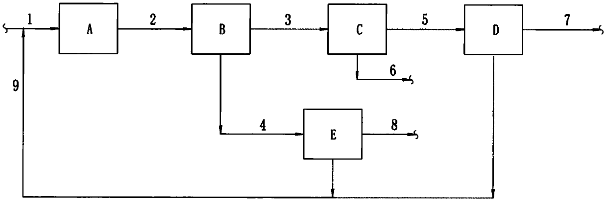
[0028] A method for removing solid impurities in catalytic oil slurry, such as figure 1 As shown, it specifically includes the following steps:

[0029] The catalytic oil slurry 1 and the solvent 9 enter the agent oil mixing unit A, and the mixed oil 2 is obtained after thorough mixing.

[0030] The mixed oil 2 passes through the centrifugal deasphalting unit B to separate the mixed oil 3 of light oil slurry and solvent and the mixed oil 4 of heavy oil slurry and solvent.

[0031] The mixed oil 4 of the heavy oil slurry and the solvent is separated through the heavy oil slurry desolventization unit E to separate the heavy oil slurry 8 and the solvent 9 .

[0032] The mixed oil 3 of light oil slurry and solvent passes through the light oil slurry filter unit C to filter out the catalyst powder 6 therein to obtain filtered light mixed oil 5 .

[0033] After filtering, the light mixed oil 5 is sent to the light oil slurry desolventization unit D to separate the light oil slurry...


PUM


Abstract

The invention provides a method for removing solid impurities from catalytic oil slurry. According to the method, an agent and oil mixing unit, a centrifugal deasphalting unit, a light oil slurry filtering unit, a light oil slurry desolventizing unit and a heavy oil slurry desolventiziing unit are arranged. Catalytic oil slurry and a solvent are completely mixed, and asphaltene in the oil slurry is removed through centrifugal separation according to different solubility, on each component of the oil slurry, of the solvent, so that the influence on oil slurry filtration by the asphaltene is reduced, the oil slurry filtration reliability is improved and long-cycle stable operation of an oil slurry filtering system is guaranteed. The solvent is recovered and recycled through the light and heavy oil slurry desolventizing units, so that consumption of the solvent is reduced.

Description

technical field [0001] The invention relates to the fields of petroleum refining and chemical industry, and more specifically relates to a method for removing solid catalyst powder from catalytic oil slurry produced by a catalytic cracking unit. Background technique [0002] With the rapid growth of the world economy, the refining technology is developing towards the lightening of heavy oil, the production of clean gasoline fuel and the production of low-carbon olefins. As the core device for processing heavy oil, the catalytic cracking unit is constantly improving its processing capacity. Oil slurry production increased accordingly. However, with the tendency of the inferior quality of catalytic raw materials and the application of catalytic blending and refining residual oil technology, the amount of catalytic slurry thrown away also increases. [0003] As a by-product of catalytic cracking unit in refinery, catalytic oil slurry has high content of aromatics and is a valu...

Claims


Application Information

Patent Timeline
Patent Type & Authority Applications(China)
IPC IPC(8): C10G53/00
CPCC10G53/00
Inventor 杨根长
Owner 北京奥博斯工程技术有限公司
Why Eureka
Try Eureka