Self-produced fuel gas combustion linkage type pyrolysis and gasification device

A technology of pyrolysis gasification and gas combustion, which is applied in the direction of gasification device feeding tool, gasification process, and production of combustible gas, which can solve the problems of high energy consumption, poor control of combustion reaction, and influence on the precipitation of combustible gas. , to achieve the effect of ensuring the precipitation effect and reducing the difficulty of cooling treatment

Pending Publication Date: 2020-02-04
NORTH CHINA UNIV OF WATER RESOURCES & ELECTRIC POWER
View PDF3 Cites 1 Cited by
  • Summary
  • Abstract
  • Description
  • Claims
  • Application Information

AI Technical Summary

Problems solved by technology

[0012] The above-mentioned technical solutions all adopt the conventional gasification furnace arrangement form of oxidation layer, reduction layer, cracking layer and drying layer. However, it is found in the application that since the gasification agent generally uses oxygen-containing normal temperature air, it is introduced into the gas from the lower part of the grate. In the gasification zone, it is difficult to control the combustion reaction, and the temperature is often too high to exceed the optimum precipitation temperature of the biomass to precipitate combustible gas, which ultimately affects the precipitation of combustible gas; and the gas export of conventional gasifiers requires the cooperation of high-power fans. Realize continuous pumping, high energy consumption

Method used


Image

  • Self-produced fuel gas combustion linkage type pyrolysis and gasification device
  • Self-produced fuel gas combustion linkage type pyrolysis and gasification device
  • Self-produced fuel gas combustion linkage type pyrolysis and gasification device

Examples


Embodiment 1

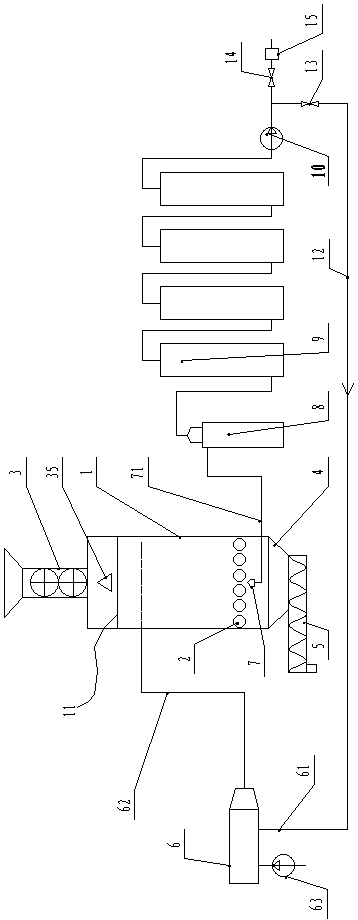
[0047] Such as figure 1 As shown, an oxygen-free medium-temperature downdraft pyrolysis device of the present invention includes a pyrolysis furnace 1, a fire grate 2 is arranged in the pyrolysis furnace 1, and a feed inlet is provided at the pyrolysis furnace 1 above the fire grate 2 , the feed inlet is equipped with a closed feeder 3, the pyrolysis furnace 1 under the grate 2 forms a slag bin 4, the slag bin is provided with a discharge port downward, and a closed feeder is provided at the discharge port. Discharger 5.

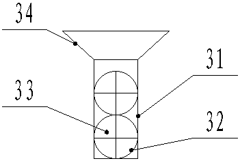
[0048] Such as figure 2 As shown, in the present embodiment, the closed feeder 3 includes a feed cylinder 31 connected to the feed port, the cross section of the feed cylinder 31 is a rectangular structure, and two horizontal cylinders are arranged tangentially up and down in the feed cylinder 31. Arranged feed roller 32, the feed roller 32 is matched and sealed with the feed cylinder 31, the feed roller 31 is arranged with an axially extending trough 33 ...

Embodiment 2

[0066] The difference between this embodiment and Embodiment 1 is that: Figure 5 As shown, the present embodiment adopts an updraft structure, the flue gas delivery pipe 62 is located below the grate 2 , and the end of the flue gas delivery pipe 62 points upward to the fire grate 2 and is connected to a medium temperature heater 64 .

[0067] In this embodiment, the medium-temperature heater 64 is a cone structure connected to the end of the flue gas conveying pipe, and the tip of the cone also points upward to the grate, and the side wall of the cone is provided with an exhaust port, so that the pyrolysis furnace 1 The uniform supply of oxygen-free medium-temperature flue gas in the pyrolysis furnace ensures the uniformity of the medium-temperature temperature field formed in the pyrolysis furnace 1.

[0068] The combustible gas collector 7 is provided with a combustible gas collecting port adjacent to the top of the pyrolysis furnace above the fire grate. In this embodimen...

Embodiment 3

[0070] The difference between this embodiment and Embodiment 1 is that: Image 6 As shown, this embodiment adopts a side suction structure, the flue gas delivery pipe 62 is located below the grate 2 , and the end of the flue gas delivery pipe 62 points upward to the fire grate 2 and is connected to a medium temperature heater 64 .

[0071] In this embodiment, the medium-temperature heater 64 is a cone structure connected to the end of the flue gas conveying pipe, and the tip of the cone also points upward to the grate, and the side wall of the cone is provided with an exhaust port, so that the pyrolysis furnace 1 The uniform supply of oxygen-free medium-temperature flue gas in the pyrolysis furnace ensures the uniformity of the medium-temperature temperature field formed in the pyrolysis furnace 1.

[0072] The combustible gas collector 7 is provided with a combustible gas collecting mechanism at the side wall above the fire grate. The combustible gas collection mechanism inc...


PUM


Abstract

The invention discloses a self-produced fuel gas combustion linkage type pyrolysis and gasification device. The self-produced fuel gas combustion linkage type pyrolysis and gasification device comprises a pyrolyzing furnace; a fire grate is arranged in the pyrolyzing furnace; the fire grate is an active fire grate; a feeding port is formed at the position of the pyrolyzing furnace above the fire grate; a closed feeder is arranged at the position of the feeding port; a discharging port is formed at the position of the pyrolyzing furnace below the fire grate; a closed discharger is arranged at the position of the discharging port; the self-produced fuel gas combustion linkage type pyrolysis and gasification device also comprises an anaerobic medium-temperature gas source mechanism which is arranged outside the pyrolyzing furnace and supplying flue gas to the pyrolyzing furnace; a combustible gas collector is arranged in the pyrolyzing furnace; the combustible gas collector is guided outof the pyrolyzing furnace through a fuel gas collecting pipeline; the fuel gas collecting pipeline is in by-pass connection with a return branch pipe; and the return branch pipe is connected with an input pipeline of the anaerobic medium-temperature gas source mechanism. According to the self-produced fuel gas combustion linkage type pyrolysis and gasification device, the self-produced fuel gas iscombusted to supply anaerobic medium-temperature flue gas to the pyrolyzing furnace, a medium-temperature temperature field is formed in the pyrolyzing furnace, and the precipitation temperature canbe effectively controlled.

Description

technical field [0001] The invention relates to the technical field of biomass pyrolysis, in particular to a self-produced gas combustion linkage type pyrolysis gasification device. Background technique [0002] Biomass gasification is under certain thermodynamic conditions, with the help of air (or oxygen) and water vapor, the high polymers of biomass are pyrolyzed, oxidized, reduced and reformed, and finally converted into carbon monoxide and hydrogen. and low molecular weight hydrocarbons and other combustible gases. [0003] The key to biomass gasification lies in the gasifier. The gasifiers currently in use include updraft, downdraft, open and fluidized bed. The reaction process of different biomass is also different. Common gasifier reactions can be divided into oxidation layer, reduction layer, cracking layer and drying layer: [0004] 1) Oxidation layer; the main reaction of biomass in the oxidation layer is oxidation reaction, the gasification agent is introduced ...

Claims


Application Information

Patent Timeline
IPC IPC(8): C10J3/00C10B53/00C10B53/07C10C5/00
CPCC10B53/00C10B53/07C10C5/00C10J3/00C10J2200/15C10J2300/1223Y02E50/10Y02P20/143
Inventor 苏钰杰赵廷林关树义
Owner NORTH CHINA UNIV OF WATER RESOURCES & ELECTRIC POWER
Why Eureka
Try Eureka