
Two-stage differential melt electrostatic spinning device

A melt electrospinning and differential technology, applied in textiles and papermaking, filament/thread forming, fiber processing, etc., can solve the problem of low solution viscosity, difficulty in batch preparation of nano-scale fibers, and feeding of micro-extruders Fast speed and other issues, to achieve the effect of scientific and reliable principle, continuous and uniform preparation, and improvement of uniformity

Active Publication Date: 2020-02-04
QINGDAO UNIV OF SCI & TECH
View PDF14 Cites 6 Cited by
  • Summary
  • Abstract
  • Description
  • Claims
  • Application Information

AI Technical Summary

Problems solved by technology

[0003] According to the different spinning media, the electrospinning technology is divided into two types: solution and melt: the solution electrospinning device does not need a heating device, the equipment is simple, and the viscosity of the solution is low, and the spun fibers are fine, but the solvent in the solution accounts for a large proportion. , the fiber output efficiency is low; melt electrospinning raw materials are 100% converted into fibers, and the efficiency is high, but due to the high viscosity of the polymer melt, the resulting fibers are relatively thick
[0004] In melt electrospinning, the micro-extruder can be used to achieve continuous and uniform feeding of micro-flow, which can achieve the purpose of continuous preparation of electrospinning, but compared with the amount of melt required for nano-scale fibers, the micro-extruder feeding The rate is still too fast to achieve batch preparation of nanofibers

Method used


Image

  • Two-stage differential melt electrostatic spinning device

Examples


Embodiment 1

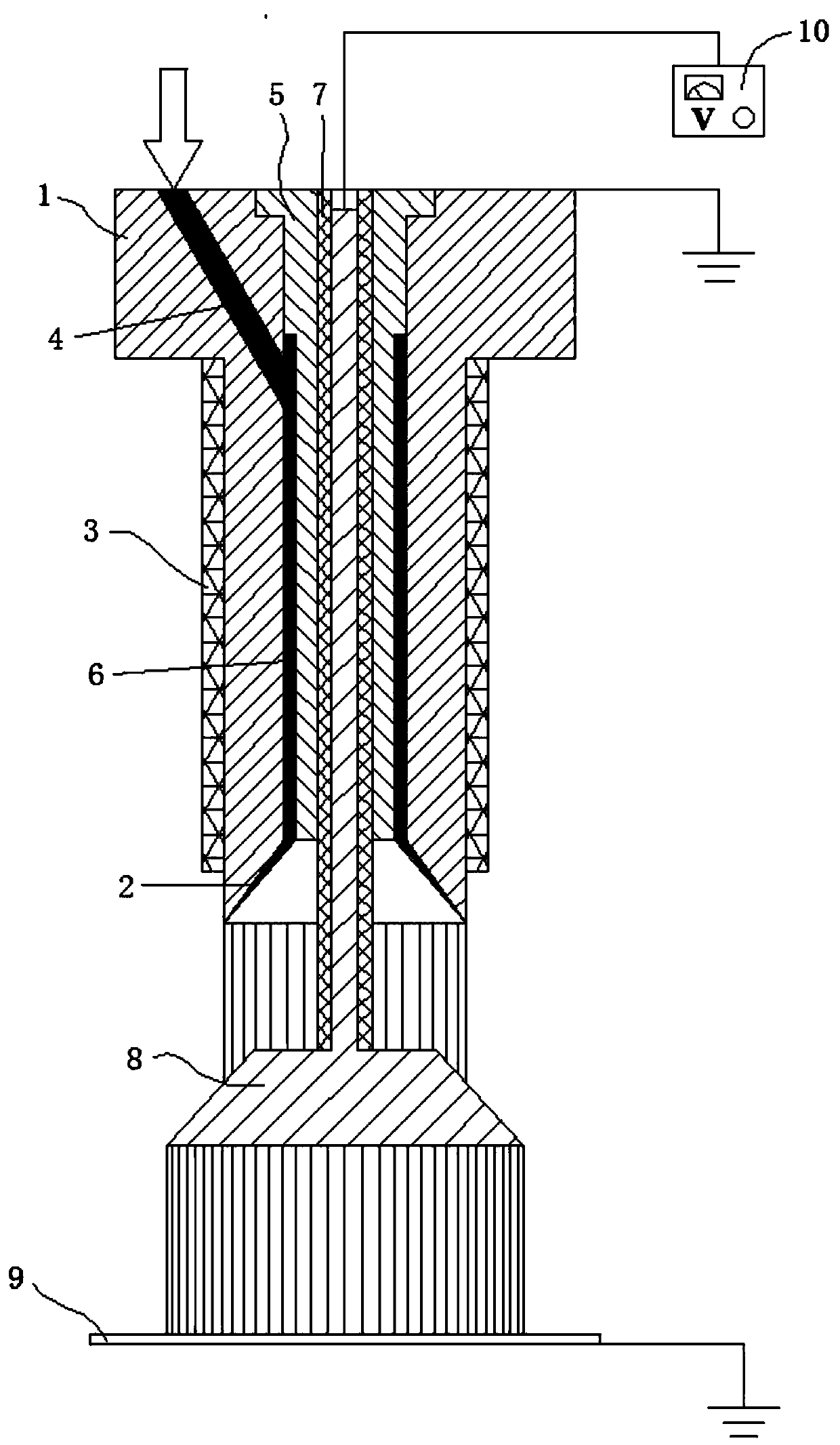
[0011] The main structure of the secondary differential melt electrospinning device involved in this embodiment includes a primary nozzle outer sleeve 1, an inner cone surface 2, an electric heating ring 3, a melt flow channel 4, a primary nozzle inner sleeve 5, Annular cavity 6, insulating ring 7, secondary spray head 8, fiber collecting plate 9 and high-voltage electrostatic generator 10; the upper diameter of the first-stage spray head outer sleeve 1 of the inner hollow cylinder structure is larger than the lower diameter, and the bottom has an inward gradually The extended inner cone surface 2, the lower periphery of the outer sleeve 1 of the first-level nozzle is provided with an electric heating ring 3, the top of the outer sleeve 1 of the first-level nozzle is provided with a melt flow channel 4 with an inclined structure, and the outer sleeve of the first-level nozzle The inside of the cylinder 1 is provided with a first-stage nozzle inner sleeve 5 with an inner hollow ...


PUM


Abstract

The invention belongs to the technical field of melt electrostatic spinning equipment, and particularly relates to a two-stage differential melt electrostatic spinning device. A main structure comprises a primary nozzle outer sleeve, an inner conical surface, an electric heating ring, a melt channel, a primary nozzle inner sleeve, an annular cavity, an insulating ring, a secondary nozzle, a fibercollecting plate and a high-voltage electrostatic generator. The two-stage nozzle structure is adopted; a polymer melt forms a jet at the bottom of the primary nozzle outer sleeve, and a second jet isformed at the bottom of the secondary nozzle; the polymer melt subjected to secondary distribution is more evenly distributed along the conical surface of the secondary nozzle; since the circumference of the bottom edge of the secondary nozzle is greater than the perimeter of the bottom of the primary nozzle outer sleeve, the number of secondary jets is increased, and the diameter is more uniform; fibers with smaller diameter and more uniform distribution are formed under the condition that the quality of the polymer melt is unchanged; and batch continuous uniform preparation of nanofibers isachieved.

Description

Technical field: [0001] The invention belongs to the technical field of melt electrospinning equipment, and in particular relates to a two-stage differential melt electrospinning device, which can realize batch-based continuous preparation of polymer nanofibers. Background technique: [0002] Electrospinning technology is an efficient nanofiber preparation technology with industrialization prospects, which can use high-voltage static electricity to make polymer melt or solution into ultrafine fibers. The prepared fibers have the advantages of small diameter, large specific surface area, and easy surface functionalization, and have received extensive attention at home and abroad. [0003] According to the different spinning media, the electrospinning technology is divided into two types: solution and melt: the solution electrospinning device does not need a heating device, the equipment is simple, and the viscosity of the solution is low, and the spun fibers are fine, but the...

Claims


Application Information

Patent Timeline
IPC IPC(8): D01D5/00
CPCD01D5/0023D01D5/0069D01D5/0076
Inventor 韩雯雯陈宏波汪传生周怡宏焦冬梅刘海超
Owner QINGDAO UNIV OF SCI & TECH
Learn More