
Electronic brake control method for electric motorcycle

A technology of electric motorcycles and electronic brakes, applied in brakes, bicycle accessories, bicycle brakes, etc., can solve the problems of reduced battery life, potential safety hazards, waste of braking energy, etc.

Active Publication Date: 2021-10-22
苏州赤兔驱动科技有限公司
View PDF8 Cites 0 Cited by
  • Summary
  • Abstract
  • Description
  • Claims
  • Application Information

AI Technical Summary

Problems solved by technology

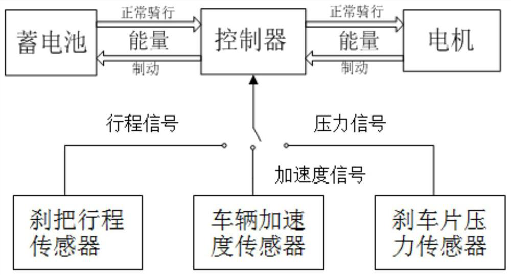
[0004] a) When the user needs high-intensity braking, such as emergency braking, the electronic braking fails to provide sufficient electromagnetic braking force, thus wasting a part of the braking energy that could have been recovered, resulting in the failure to maximize the cruising range of the vehicle; and If the electromagnetic braking force is too small, it may be difficult to provide additional high-intensity braking force to assist braking when the mechanical braking force is insufficient, which may pose a certain safety hazard;
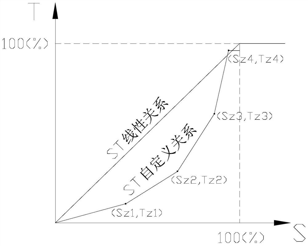
[0005] b) When the user needs low-intensity braking, such as a small braking force to assist the vehicle to stop in front of the zebra crossing, the electronic brake provides excessive electromagnetic braking force, which makes the user experience a bad driving experience of sudden forward rush; and in extreme Under certain conditions, excessive electromagnetic braking force may also cause certain potential safety hazards;
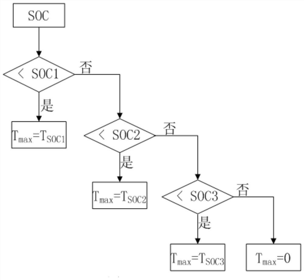
[0006] c) The maximum electromagnetic braking force that the battery allows the motor to provide is different under different SOCs. If the actual electromagnetic braking force exceeds the maximum allowable electromagnetic braking force, the service life of the battery will be greatly reduced

Method used


Image

  • Electronic brake control method for electric motorcycle
  • Electronic brake control method for electric motorcycle
  • Electronic brake control method for electric motorcycle

Examples


Embodiment

[0022] See attached Figure 1-3 As shown, an electronic brake control method for electric motorcycles of the present invention includes the following steps: step S1, the controller collects the brake signal of the mechanical brake through the signal acquisition unit; step S2, the controller according to the real-time SOC threshold of the battery Determine the maximum electromagnetic braking force Tmax that is allowed to be output by the motor; step S3, the controller constructs a braking signal conversion model according to the maximum electromagnetic braking force Tmax in S2; step S4, the controller converts the braking signal collected by S1 into The target electromagnetic braking force Tt; step S5, the controller controls the motor to output the target electromagnetic braking force Tt.

[0023] In step S1, when the vehicle is mechanically braked, the human hand will press the brake lever. At this time, the brake pad will be under corresponding pressure, and the acceleration...


PUM


Abstract

The invention discloses an electronic brake control method for electric motorcycles, comprising the following steps: step S1, the controller collects the brake signal of the mechanical brake through the signal acquisition unit; step S2, the controller judges the The maximum electromagnetic braking force Tmax that is allowed to be output by the motor; step S3, the controller constructs a braking signal conversion model according to the maximum electromagnetic braking force Tmax in S2; step S4, the controller converts the braking signal collected by S1 into the target electromagnetic braking force according to the braking signal conversion model Braking force Tt; step S5, the controller controls the motor to output the target electromagnetic braking force Tt. The electronic brake control method of the present invention can control the electronic brake to generate electromagnetic braking force matching the user's demand in real time, which not only ensures the safety and comfort of driving, but also can recover the braking energy to the greatest extent.

Description

technical field [0001] The invention relates to the technical field of vehicle control, in particular to an electronic brake control method for electric motorcycles. Background technique [0002] The electronic braking system means that when the electronic control system detects mechanical braking, it turns the motor into a generator, thereby generating additional electromagnetic braking force through the generator current to enhance the braking effect, and recharging it into the battery for recycling. kinetic energy and increase the cruising range. [0003] Electric motorcycles have different requirements for braking strength and braking distance under different driving conditions. In mechanical brakes, the braking strength is usually controlled by the force with which the user presses the mechanical brake lever. However, the electronic braking force of existing electric motorcycles is difficult to adjust, resulting in the following problems: [0004] a) When the user nee...

Claims


Application Information

Patent Timeline
Patent Type & Authority Patents(China)
IPC IPC(8): B60T8/17B62L3/00
CPCB60T8/1706B62L3/00
Inventor 荣睿吴道贤雷吉
Owner 苏州赤兔驱动科技有限公司
Learn More