Temperature control system and method applied to spectrophotometer analysis instrument

A temperature control method and spectrophotometer technology, which are used in temperature control, control/regulation systems, material analysis by optical means, etc., can solve the problems of complex system design, sudden change in power load, and difficulty in rapid adjustment, and achieve system structure. Simple, widely used, stable output effect

Inactive Publication Date: 2020-02-07
杭州浅海科技有限责任公司
View PDF6 Cites 0 Cited by
  • Summary
  • Abstract
  • Description
  • Claims
  • Application Information

AI Technical Summary

Problems solved by technology

However, the PWM control method also has its inherent disadvantages: since the voltage controlled by PWM is generally large, the heat provided in the constant temperature stage is large, and it is easy to exceed the required temperature control accuracy; to achieve microsecond-level precise control, the CPU takes time long, unable to take into account the execution of other functions; the load of the power supply changes frequently, which affects the stability of other signals and has potential damage to the power supply
[0011] The advantages of the PID control method include: a wide range of applications, strong system adaptability; it can eliminate the overshoot phenomenon on the temperature; correspondingly, PID also has its own disadvantages: the system design is complicated, and the model parameters need to be set according to the system characteristics, and real-time It takes a certain amount of time to adjust the parameters to adapt to system changes; a complex hardware foundation is required to fully send back the efficacy of PID, and the application of instruments with certain requirements for volume, complexity, and power consumption is limited; to meet the needs The time of the constant temperature stage is limited; when the important variables of the system change, it is difficult to adjust quickly

Method used


Image

  • Temperature control system and method applied to spectrophotometer analysis instrument
  • Temperature control system and method applied to spectrophotometer analysis instrument
  • Temperature control system and method applied to spectrophotometer analysis instrument

Examples


Embodiment 1

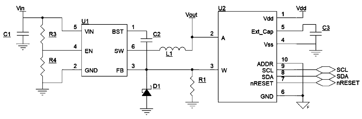
[0031] The temperature control system includes the following parts:

[0032] 1) Water pipe - the water pipe is the part of the heating component that contains the liquid. The cross-sectional area of ​​the liquid inside it is S, and the length of the water pipe is L. In the instrument design stage, determine the values ​​of S and L according to the site application requirements;

[0033] 2) Heating wire—the heating wire is wound on the water pipe, and the outside is protected by an insulating layer. It is used as a heating source to heat the liquid. The voltage at both ends is v, and the resistance is R. In the instrument design stage, determine the R value, as well as the maximum and minimum values ​​of v according to the field application requirements;

[0034] 3) Power supply and control circuit—provide voltage for the heating wire. Here, an adjustable voltage source chip is used. The output voltage is determined by the ratio of two resistors, and can be adjusted between the...

Embodiment 2

[0082] When the liquid is still in the water pipe, the liquid is in a static state, and the steps and derivation formulas in Embodiment 1 are fully applicable. In the application process, the temperature control method includes the following steps:

[0083] 1) In the application state, measure and record the temperature rise-voltage relationship, fit the temperature rise-voltage relationship curve, and store the original data and curve formula in the programmable processor chip;

[0084] 2), according to the temperature rise-voltage relationship curve in step 1), apply the required temperature rise voltage, and heat up to the target temperature range;

[0085] 3), according to the temperature rise-voltage relationship curve in step 1), apply the required constant temperature voltage to keep the temperature within the target temperature range;

[0086] 4) The temperature sensor monitors the temperature of the heated liquid in real time, and the programmable processor chip adju...

Embodiment 3

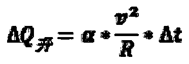
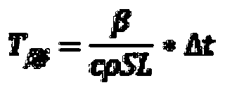
[0088] When the liquid in the water pipe starts to flow, the previous thermodynamic model needs to be further decomposed to determine the influencing factors. Consider the temperature rise of the liquid part entering the water pipe within a small time period Δt, as follows

[0089]

[0090] where A is the flow rate of the liquid, which is a constant in most applications.

[0091] It can be seen that when the liquid flows dynamically, on the basis of the various steps and derivation formulas in Example 1, the factors affecting the temperature difference increase the flow rate of a liquid.

[0092] In the application process, the temperature control method includes the following steps:

[0093] 1) Keeping the flow rate at different definite values, performing multiple measurements and recording, fitting each temperature rise-voltage relationship curve, and storing the original data and curve formula in the programmable processor chip;

[0094] 2), according to the temperatu...


PUM


Abstract

The invention relates to the field of ocean analysis, and discloses a temperature control system and method applied to spectrophotometer analysis instrument. The temperature control system is simple in structure and wide in application. According to the temperature control method, temperature rising and voltage are calibrated, temperature rising and constant temperature control is performed by a special voltage according to the obtained function, stable output is achieved, and meanwhile, the time of a CPU occupied by a temperature control function is also relatively small. Moreover, accordingto the temperature control method, an output voltage of an adjustable voltage source chip is adjusted by a programmable resistor, namely, the constant-temperature accuracy control is adjusted by adjusting a voltage of an electrical heating wire, and the accuracy is relatively high.

Description

technical field [0001] The invention relates to the field of ocean analysis, in particular to a temperature control system and method used in spectrophotometer analysis instruments. Background technique [0002] The spectrophotometer method is a method to measure the concentration of a solution through the absorbance value of the solution, and its most important theoretical basis is Lambert's law. In order to apply the spectrophotometer method, it is necessary to select one or several chemical reagents according to the characteristics of the substance to be tested, and carry out a chemical reaction with the sample in a certain sequence and time requirements to produce a chromogenic solution with a certain absorbance, and then use The formula of Lambert's law is used to derive the molar concentration (or mass concentration) of the substance to be measured. In the application of this method, the temperature during the chemical reaction has an important impact on the accuracy ...

Claims


Application Information

Patent Timeline
Patent Type & Authority Applications(China)
IPC IPC(8): G05D23/24G01N21/01G01N21/31
CPCG01N21/01G01N21/31G05D23/24
Inventor 童海明桑泉刘鹏姜飞于恩伟
Owner 杭州浅海科技有限责任公司
Why Eureka
Try Eureka