
A New Heat Dissipating Electric Spindle

A technology of electric spindles and spindles, which is applied in the direction of electromechanical devices, electrical components, electric components, etc., can solve the problems of damage to electric spindles, easy oil leakage, high production costs, etc., and achieve improved heat conduction and heat dissipation performance, simple overall structure and low production costs. low effect

Active Publication Date: 2021-11-09
ANYANG INST OF TECH
View PDF0 Cites 0 Cited by
  • Summary
  • Abstract
  • Description
  • Claims
  • Application Information

AI Technical Summary

Problems solved by technology

If the temperature of the spindle is not controlled, the thermal and dynamic characteristics of the built-in motor will deteriorate, affect the normal operation of the electric spindle, and even damage the electric spindle
[0003] The current heat dissipation method of the electric spindle is mainly water cooling or oil cooling, which takes away part of the heat through forced circulation of water or oil inside the electric spindle, but both water cooling and oil cooling require the design of condensing pipes and external coolant tanks. Complicated, high production cost, and the oil cooling has high requirements on the sealing of the electric spindle, which is prone to oil leakage

Method used


Image

  • A New Heat Dissipating Electric Spindle
  • A New Heat Dissipating Electric Spindle
  • A New Heat Dissipating Electric Spindle

Examples


Embodiment Construction

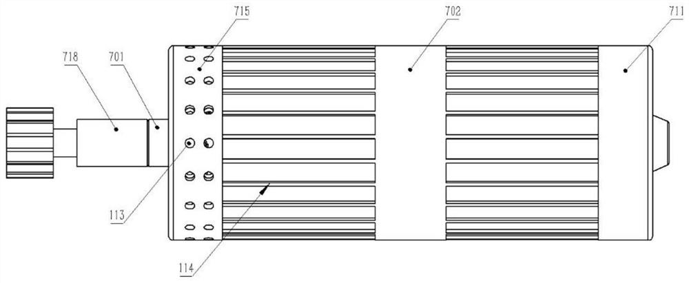
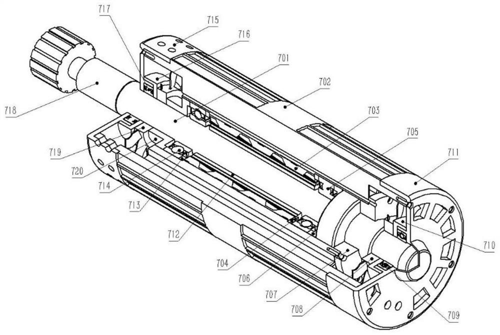
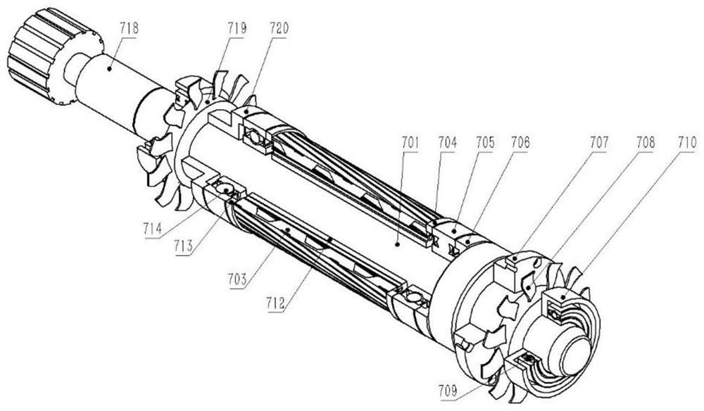
[0030] The technical solutions of the present invention will be further described in detail below in conjunction with the accompanying drawings and embodiments. For ease of description, in this embodiment, the position where the ventilation end cover II is located is defined as "front", and the position where the ventilation end cover I is located is defined as "rear".

[0031] see Figure 1 to Figure 4 In this embodiment, a new heat-dissipating electric spindle includes a spindle 701, a ventilated shell 702 made of brass, a stator 703, four bearings, three washers, and a lock nut 707, which are made of 1Cr12Mo heat-resistant steel or chromium alloy or Two cooling fans, two sealing rings, two ventilation end covers, and rotors made of titanium alloy are manufactured through lathe processing, forging, milling, etc. The surface strength hardening treatment is carried out on the blades of the heat dissipation fan. The specific assembly relationship of each part is as follows: ...


PUM


Abstract

A new heat-dissipating electric spindle, including the main shaft, the ventilation shell set on the outside of the main shaft, the ventilation end cover I and the ventilation end cover II fixed on both ends of the ventilation shell. , main shaft sleeve, bearing Ⅲ, retaining ring Ⅱ, rotor, retaining ring Ⅰ, bearing Ⅰ, washer, lock nut, cooling fan Ⅰ, bearing Ⅱ, bearing Ⅳ is fixed on the ventilation end cover Ⅱ through the sealing ring Ⅱ, and the ventilation shell The inner wall is equipped with a stator, and the bearing II is fixed on the ventilation end cover I through the sealing ring I; the ventilation end cover I is provided with a ventilation window, and the ventilation end cover II is provided with a ventilation hole, and the inside of the ventilation shell is provided with The ventilation channel and the outer wall are provided with cooling ribs. The electric spindle proposed by the present invention adopts the cooperation of double cooling fans and ventilation windows, ventilation ducts, ventilation holes and cooling ribs to realize multiple and effective heat dissipation, and the ventilation shell is made of brass to further improve its heat conduction and heat dissipation performance.

Description

technical field [0001] The invention belongs to the technical field of electric spindles, and in particular relates to an electric spindle adopting a new heat dissipation structure. Background technique [0002] At present, electric spindles are more and more widely used in the field of mechanical engineering, and the heat dissipation problem is always the object that needs to be solved in the design of an electric spindle. When the existing electric spindle is working, its heat source mainly comes from the heat generated by the built-in motor and the spindle bearing. If the temperature of the spindle is not controlled, the thermal characteristics and dynamic characteristics of the built-in motor will be deteriorated, which will affect the normal operation of the electric spindle and even damage the electric spindle. [0003] The current heat dissipation method of the electric spindle is mainly water cooling or oil cooling, which takes away part of the heat through forced c...

Claims


Application Information

Patent Timeline
Patent Type & Authority Patents(China)
IPC IPC(8): H02K9/06H02K5/20H02K5/18H02K5/02
CPCH02K5/02H02K5/18H02K5/20H02K9/06
Inventor 何强任路文游志恒董晓阳郑博王广飞周新宇亓明张勇
Owner ANYANG INST OF TECH
Learn More