
Pipe preheating device and reheating method thereof

A technology of preheating device and pipe, which is applied in the field of heat treatment, can solve the problems of increasing the heating energy consumption of the preheating furnace, oxidation of the workpiece surface, and reducing the temperature in the furnace, so as to improve work efficiency, smooth preheating treatment, and ensure continuous production Effect

Active Publication Date: 2020-02-11
山东中安弘安全科技集团有限公司 +1
View PDF3 Cites 6 Cited by
  • Summary
  • Abstract
  • Description
  • Claims
  • Application Information

AI Technical Summary

Problems solved by technology

The common pipe preheating method uses the whole furnace to heat multiple steel pipes at the same time, but each time the furnace is opened to take the workpiece, air will enter the heating furnace, causing the surface of the workpiece to oxidize, affecting subsequent processing and use
In addition, cold air entering the heating furnace will also reduce the temperature in the furnace and increase the heating energy consumption of the preheating furnace

Method used

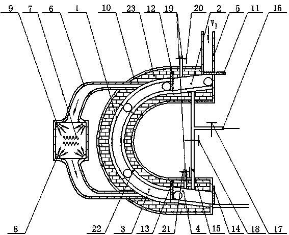
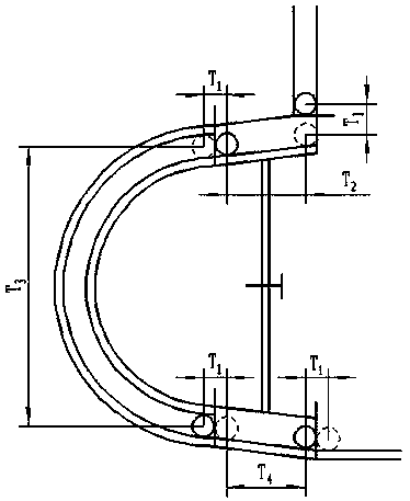
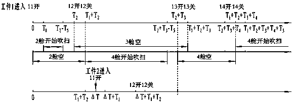

Image

  • Pipe preheating device and reheating method thereof
  • Pipe preheating device and reheating method thereof
  • Pipe preheating device and reheating method thereof

Examples


Embodiment 1

[0068] Determine the workpiece heating time T=38.5s and the interval between two workpieces according to the processing conditions of the production line △T=32s, T1=0.5s, T2=4s, T3=30s, T4=4s, T5=2s, when the workpiece heating cabin 2 is at the same time When the number of heated workpieces n is 1;

[0069] The controller automatically calculates the opening time of the hatch;

[0070] The resistance wire 7 in the heat transfer channel 6 is heated, the blower 9 and the exhaust fan 8 are started, the hot air flow enters the workpiece heating cabin 3 from the heat transfer channel 6, and the hot air flow between the heat transfer channel 6 and the workpiece heating cabin 3 circulates continuously;

[0071] When the first workpiece is put into the workpiece entering channel 5, the system starts timing, and the No. 1 cabin door 11 remains open. After 0.5s, after the workpiece enters the workpiece entering cabin 2, the No. 1 cabin door 11 closes;

[0072] At 1s, the No. 3 valve 13...

Embodiment 2

[0083] Determine the workpiece heating time T=38.5s and the interval between two workpieces according to the processing conditions of the production line △T=24s, T1=0.5s, T2=4s, T3=30s, T4=4s, T5=2s, when the workpiece heating cabin 3 is at the same time When the number of heated workpieces n is 2;

[0084] The controller automatically calculates the opening time of the hatch;

[0085] The resistance wire 7 in the heat transfer channel 6 is heated, the blower 9 and the exhaust fan 8 are started, the hot air flow enters the workpiece heating cabin 3 from the heat transfer channel 6, and the hot air flow between the heat transfer channel 6 and the workpiece heating cabin 3 circulates continuously;

[0086] When the first workpiece is put into the workpiece and enters the channel 5, the system starts timing, and the No. 1 cabin door 11 remains open. When 0.5s, as soon as the workpiece enters the workpiece entering cabin 2, the No. 1 cabin door 11 is closed; image 3 Shown, where...


PUM


Abstract

The invention discloses a pipe preheating device and a preheating method of the pipe preheating device, and belongs to the field of heat treatment. The pipe preheating device comprises a preheating shell and a heat transfer channel. The preheating shell is internally provided with a C-shaped slideway. The heat transfer channel communicates with the C-shaped slideway. The C-shaped slideway comprises a workpiece inlet cabin at the upper end, a workpiece heating cabin at the middle segment and a workpiece preset cabin at the lower end. The workpiece inlet cabin is connected with a workpiece inletchannel. The workpiece preset cabin is connected with a subsequent production line. Inlets and outlets of the workpiece inlet cabin, the workpiece heating cabin and the workpiece preset cabin are provided with doors which can be controlled by a controller to be opened and closed. By means of the pipe preheating device and the preheating method of the pipe preheating device, a workpiece is prevented from being oxidized during preheating, and the utilization rate of preheated nitrogen is further improved.

Description

technical field [0001] The invention relates to the field of heat treatment, in particular to a pipe preheating device and a preheating method thereof. Background technique [0002] In order to prevent the workpiece from being heated unevenly due to the rapid temperature rise of the workpiece, the pipe needs to be pre-heated to the specified temperature before heat treatment. The common pipe preheating method uses the whole furnace to heat multiple steel pipes at the same time, but each time the furnace is opened to take the workpiece, air will enter the heating furnace, causing the surface of the workpiece to oxidize, affecting subsequent processing and use. In addition, cold air entering the heating furnace will also reduce the temperature in the furnace and increase the heating energy consumption of the preheating furnace. Contents of the invention [0003] The technical problem to be solved in the present invention is to provide a pipe preheating device and a preheati...

Claims


Application Information

Patent Timeline
Patent Type & Authority Applications(China)
IPC IPC(8): C21D9/08C21D1/74
CPCC21D1/74C21D9/08
Inventor 韩毅肖瑶
Owner 山东中安弘安全科技集团有限公司
Learn More