Hydrogen oil transportation system

A technology of hydrogen oil and oil recovery, which is applied in pipeline system, fluid treatment, gas treatment/storage, etc., and can solve problems such as the imbalance between supply and demand of hydrogen energy

Active Publication Date: 2020-02-11
YUNNAN POWER GRID CO LTD ELECTRIC POWER RES INST
View PDF4 Cites 4 Cited by
  • Summary
  • Abstract
  • Description
  • Claims
  • Application Information

AI Technical Summary

Problems solved by technology

[0005] This application provides a hydrogen oil transportation system to solve the technical problem of unbalanced supply and demand of hydrogen energy

Method used


Image

  • Hydrogen oil transportation system
  • Hydrogen oil transportation system

Examples


Embodiment approach

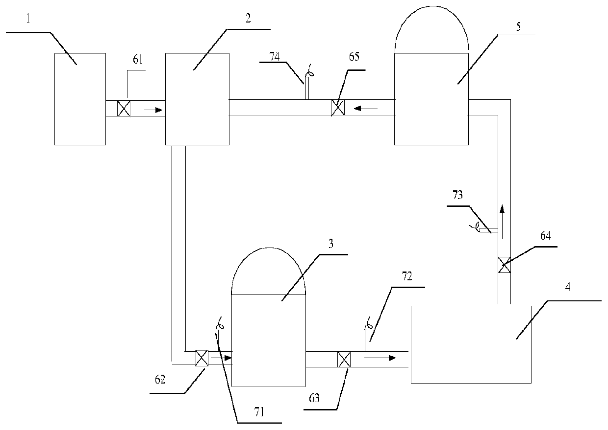
[0046] The specific embodiment is as follows: the comparison circuit acquires the pipeline flow values ​​of the third flowmeter 73 and the second flowmeter 72, and calculates the pipeline flow of the third flowmeter 73 minus the second flowmeter 72 difference and send the difference in pipe flow to the trigger circuit. The trigger circuit receives the pipeline flow difference information, if the difference reaches the threshold -5m 3 , the trigger circuit triggers the switch of the second solenoid valve 62 to open the second solenoid valve 62 so that the hydrogen oil in the hydrogenation device 2 flows to the hydrogen oil filling station 4 . When the pipeline flow difference is less than the threshold -5m 3 , the second solenoid valve 62 is closed. The control details between other flowmeters and solenoid valves are similar to this according to the relationship between the hydrogen oil outflow and inflow of the device, and will not be repeated one by one.

[0047] The diffe...


PUM


Abstract

The invention discloses a hydrogen oil transportation system including a hydrogen production device, a hydrogenation device, a hydrogen oil storage station, a hydrogen oil filling station and a recovery oil storage station. The hydrogen oil storage station includes at least one hydrogen oil storage tank, and the recovery oil storage station includes at least one recovery oil storage tank; hydrogenoil in the hydrogen production device and the recovery oil storage station flows to the hydrogenation device, gaseous hydrogen is stored in organic liquid through a catalytic hydrogenation reaction,and the hydrogen oil is formed; the hydrogen oil flows from the hydrogenation device to the hydrogen oil storage station to be stored and then flows to the hydrogen oil filling station; hydrogen is separated from the organic liquid through a catalytic dehydrogenation reaction by means of the hydrogen oil filling station to be used in a manner of gaseous hydrogen; and dehydrogenated organic liquidflows to the recovery oil storage station as recovery oil and then flows from the recovery oil storage station to the hydrogenation device. Connection between hydrogen oil production and hydrogen oilrecovery is realized, balance between supply and demands is realized, and the energy loss of traditional on-board transportation is reduced.

Description

technical field [0001] This application relates to the field of hydrogen energy production and transportation, in particular to a hydrogen oil transportation system. Background technique [0002] As a green energy, hydrogen energy has received extensive attention in recent years. At present, the production and transportation of hydrogen energy are mainly in the form of gaseous hydrogen, which faces safety problems such as explosions during hydrogen transportation and storage. [0003] In order to solve the above problems, an organic liquid hydrogen storage technology has been developed in recent years, that is, gaseous hydrogen is stored in organic liquid through catalytic hydrogenation reaction to form hydrogen oil. Under normal temperature and pressure, hydrogen is stably stored in hydrogen oil liquid, which is convenient for transportation; when in use, hydrogen is extracted from organic liquid through catalytic dehydrogenation reaction, and used in the form of gaseous h...

Claims


Application Information

Patent Timeline
Patent Type & Authority Applications(China)
IPC IPC(8): F17D1/02F17D1/04
CPCF17C2221/012F17C2223/04F17C2225/0123F17C2260/02F17D1/02F17D1/04Y02E60/32Y02E60/34
Inventor 刘荣海郭新良郑欣杨迎春许宏伟孔旭晖何运华周静波虞鸿江宋玉锋焦宗寒陈国坤杨雪滢程雪婷李宗红代克顺
Owner YUNNAN POWER GRID CO LTD ELECTRIC POWER RES INST
Why Eureka
Try Eureka