Evaporation source assembly

An evaporation source and component technology, which is applied in vacuum evaporation plating, ion implantation plating, metal material coating process, etc., can solve the problems of high AMOLED production cost, lower utilization rate of doping materials, uneven doping, etc. problems, to achieve the effects of reducing evaporation costs, promoting doping, and improving utilization

Active Publication Date: 2020-02-14
信利(仁寿)高端显示科技有限公司
View PDF7 Cites 0 Cited by
  • Summary
  • Abstract
  • Description
  • Claims
  • Application Information

AI Technical Summary

Problems solved by technology

The existing evaporation source components are not uniformly doped in the actual evaporation process, which reduces the utilization rate of doped materials. The current evaporation utilization rate of organic light-emitting materials is only 5-30%, and most of them are deposited in the evaporation chamber. And waste, which is also one of the main reasons for the high production cost of AMOLED

Method used


Image

  • Evaporation source assembly
  • Evaporation source assembly
  • Evaporation source assembly

Examples


Embodiment 1

[0030] The applicant found that in the evaporation process, since it is necessary to achieve a certain doping ratio by controlling the evaporation rate of different materials, the evaporation rate of the host material is generally 2~10Å / s in the evaporation process, while the doping The evaporation rate of the material is 0.02~0.1 Å / s, which is very different.

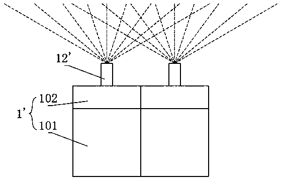
[0031] Currently used evaporation sources, the structures of the evaporation sources used for the host material and the dopant material are almost the same, and when performing evaporation, the upper end surfaces of the nozzles are all at the same height. In the actual evaporation process, since the evaporation rate of the host material is much greater than that of the dopant material, the evaporation sublimation flow of the host material will impact the sublimation flow of the dopant material, which causes uneven doping and reduces the Utilization of dopant materials.

[0032] Thus, the present embodiment provides an...

Embodiment 2

[0042] This embodiment is an improved solution of Embodiment 1.

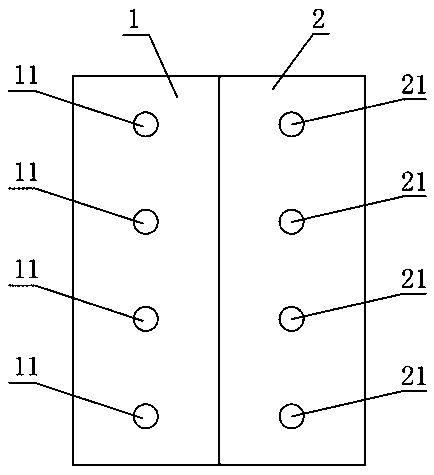
[0043] After the nozzle 21 of the B evaporation source is lengthened in the first embodiment, the dopant material is easily cooled and blocked at the nozzle. For improvement, a heater is provided at the B evaporation source nozzle 21 in this embodiment.

[0044] Such as Figure 4 As shown, the heater can be a resistive heater (such as a heating wire), and the resistive heater can be arranged on the outside or inside of the B evaporation source nozzle 21, and the heater can be specifically designed according to the shape and size of the nozzle.

[0045] The heater may also be a laser heater or the like. A laser heater may be provided outside the B evaporation source nozzle 21 .

Embodiment 3

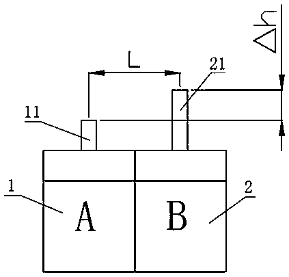
[0047] In this embodiment, the evaporation rate at the nozzle 11 of the evaporation source A is greater than the evaporation rate at the nozzle 21 of the evaporation source B.

[0048] Such as Figure 5 As shown, the difference from the first and second embodiments is that in this embodiment, the A evaporation source 1 and the B evaporation source 2 have the same structure. That is, the height of the body itself and the length of the nozzle are the same. When arranging, the B evaporation source 2 is lifted up so that the height of the B evaporation source 2 is greater than the height of the A evaporation source 1. In this way, the upper end surface of the B evaporation source nozzle 21 can be higher than the A evaporation source nozzle 11. end face. The advantage of this is that the B evaporation source nozzle 21 does not need to be designed to be lengthened, and the B evaporation source nozzle 21 will not be easily blocked, and no additional heater is required.


PUM


Abstract

The invention discloses an evaporation source assembly which is composed of at least two evaporation sources. Each evaporation source includes a body and a nozzle arranged on the body. The upper end face f the nozzle of at least one of the evaporation sources is higher than the upper end faces of the nozzles of the other evaporation sources. According to the evaporation source assembly, the upperend faces of the nozzles with the small evaporation rate are higher than the upper end faces of the nozzles with the large evaporation rate, so that the air flow of the nozzles with the large rate assist the air flow of the nozzles with the small rate in sublimation, doping of gases with different material is promoted, the utilization rate of the doped materials is improved, and the evaporation cost is reduced.

Description

technical field [0001] The invention relates to the technical field of evaporation, and more specifically relates to an evaporation source assembly. Background technique [0002] When making the organic light-emitting layer of AMOLED, it generally consists of a host material (host) and a dopant material (dopant), or a host material and two dopant materials, or two host materials and a dopant material. Combination of miscellaneous materials and other materials by vapor deposition. [0003] Due to the different synthesis and purification processes of various materials, the unit price of different materials varies greatly. For example, the unit price of doped materials is 10 times or even 100 times that of the main material. The proportion of the host material and the dopant material in each organic light-emitting layer is different. Generally, the dopant material is only 1% to 12% of the host material. [0004] Such as figure 1 As shown, the existing evaporation source asse...

Claims


Application Information

Patent Timeline
IPC IPC(8): C23C14/24C23C14/12
CPCC23C14/24C23C14/12
Inventor 李志荣谢志生马亮
Owner 信利(仁寿)高端显示科技有限公司
Why Eureka
Try Eureka