
Duty ratio design method and system for eliminating current sampling interference, medium and equipment

A technology of current sampling and design method, which is applied in the field of frequency conversion control to achieve the effects of stable speed, improved system efficiency, and improved precision and accuracy

Active Publication Date: 2020-02-14
RUKING EMERSON CLIMATE TECH SHANGHAI CO LTD
View PDF5 Cites 5 Cited by
  • Summary
  • Abstract
  • Description
  • Claims
  • Application Information

AI Technical Summary

Problems solved by technology

[0006] In view of the shortcomings of the prior art described above, the purpose of the present invention is to provide a duty cycle design method, system, medium and equipment for eliminating current sampling interference, which is used to solve the problem that the prior art cannot ensure system response speed and low hardware Under the condition of low cost, eliminate the problem of current sampling interference generated when PFC and frequency converter are used at the same time

Method used


Image

  • Duty ratio design method and system for eliminating current sampling interference, medium and equipment
  • Duty ratio design method and system for eliminating current sampling interference, medium and equipment
  • Duty ratio design method and system for eliminating current sampling interference, medium and equipment

Examples


Embodiment 1

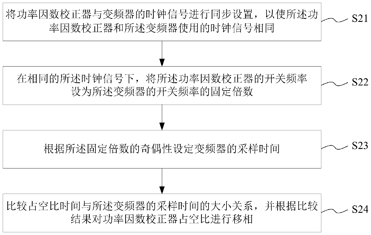
[0035] This embodiment provides a duty cycle design method for eliminating current sampling interference. The duty cycle design method for eliminating current sampling interference includes:

[0036] Synchronously setting the power factor corrector and the clock signal of the frequency converter, so that the power factor corrector and the frequency converter use the same clock signal;

[0037] Setting the switching frequency of the power factor corrector to a fixed multiple of the switching frequency of the inverter under the same clock signal;

[0038] Setting the sampling time of the frequency converter according to the parity of the fixed multiple;

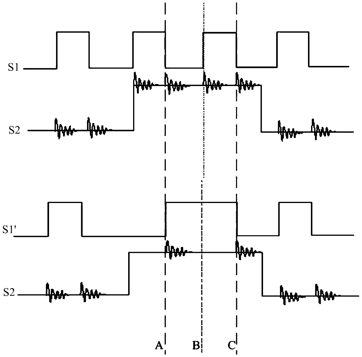
[0039] The relationship between the duty cycle time and the sampling time of the inverter is compared, and the power factor corrector duty cycle is phase-shifted according to the comparison result; the duty cycle time and the power factor corrector duty cycle are based on The switching period of the power factor corrector is determined...

Embodiment 2

[0063] This embodiment provides a duty cycle design system for eliminating current sampling interference, and the duty cycle design system for eliminating current sampling interference includes:

[0064] The clock synchronization module is used to synchronize the clock signal of the power factor corrector and the frequency converter, so that the power factor corrector and the frequency converter use the same clock signal;

[0065] A period setting module, configured to set the switching frequency of the power factor corrector to a fixed multiple of the switching frequency of the inverter under the same clock signal;

[0066] The sampling time setting module is used to set the sampling time of the frequency converter according to the parity of the fixed multiple;

[0067] The phase shift module is used to compare the relationship between the duty cycle time and the sampling time of the frequency converter, and to phase shift the duty cycle of the power factor corrector according to the ...

Embodiment 3

[0081] This embodiment provides a device including: a processor, a memory, a transceiver, a communication interface or / and a system bus; the memory and the communication interface are connected to the processor and the transceiver through the system bus to complete mutual communication, and the memory is used for A computer program is stored, the communication interface is used to communicate with other devices, and the processor and the transceiver are used to run the computer program to make the device execute the steps of the duty cycle design method for eliminating current sampling interference.

[0082] Specifically, the device includes: a processor, a memory, a transceiver, a communication interface or / and a system bus; the memory and the communication interface are connected to the processor and the transceiver through the system bus and communicate with each other, and the memory is used to store the computer The program and the communication interface are used to communic...


PUM


Abstract

The invention provides a duty ratio design method and system for eliminating current sampling interference, a medium and equipment. The duty ratio design method for eliminating current sampling interference comprises the following steps: synchronizing the clock signal of a power factor corrector with the clock signal of a frequency converter to enable the clock signals used by the power factor corrector and the frequency converter to be the same; under the same clock signal, setting the switching frequency of the power factor corrector to be a fixed multiple of the switching frequency of the frequency converter; setting the sampling time of the frequency converter according to the parity of the fixed multiple; and obtaining the size relationship between the duty ratio time and the samplingtime of the frequency converter through comparison, and performing phase shift on the duty ratio of the power factor corrector according to the comparison result, wherein the duty ratio time and theduty ratio of the power factor corrector are determined according to the switching period of the power factor corrector. Through the PFC duty ratio control method provided by the invention, the problem of current sampling interference generated in an occasion where the PFC and the frequency converter are used at the same time is solved.

Description

Technical field [0001] The invention belongs to the field of frequency conversion control, and relates to a duty cycle design method, in particular to a duty cycle design method, system, medium and equipment for eliminating current sampling interference. Background technique [0002] At present, frequency conversion technology is widely used in motor control. When it is integrated into the power grid, active PFC (Power Factor Correction, power factor corrector) is required to reduce harmonic interference to the power grid. In PFC and inverter design, current sampling is a key factor related to control performance and reliability. [0003] Active power correction and frequency conversion technology are generally implemented based on pulse width modulation PWM. Due to the use of switching devices, pulse interference will be generated at the time of opening and closing. For step-up PFC, current sampling is performed at the middle moment when the switching tube is turned on or off; f...

Claims


Application Information

Patent Timeline
IPC IPC(8): H02M1/00H02M1/42
CPCH02M1/00H02M1/42H02M1/0009Y02B70/10
Inventor 林石裕张璇璇颜道丹
Owner RUKING EMERSON CLIMATE TECH SHANGHAI CO LTD
Learn More