Millimeter wave printed dipole antenna array radiating element and array antenna

A dipole antenna and radiating unit technology, applied in the antenna array, radiating element structure, antenna and other directions, can solve the problems of narrow frequency band, inconvenient power feeding, small antenna size, etc., to achieve enhanced radiation and receiving capabilities, and convenient Feed, easy processing effect

Inactive Publication Date: 2020-02-18
BEIJING INST OF RADIO MEASUREMENT
View PDF3 Cites 4 Cited by
  • Summary
  • Abstract
  • Description
  • Claims
  • Application Information

AI Technical Summary

Problems solved by technology

Its structure is that on the dielectric substrate perpendicular to the metal reflector, a dipole antenna is printed on one side, and a matching feeder is printed on the o

Method used


Image

  • Millimeter wave printed dipole antenna array radiating element and array antenna
  • Millimeter wave printed dipole antenna array radiating element and array antenna
  • Millimeter wave printed dipole antenna array radiating element and array antenna

Examples


Embodiment Construction

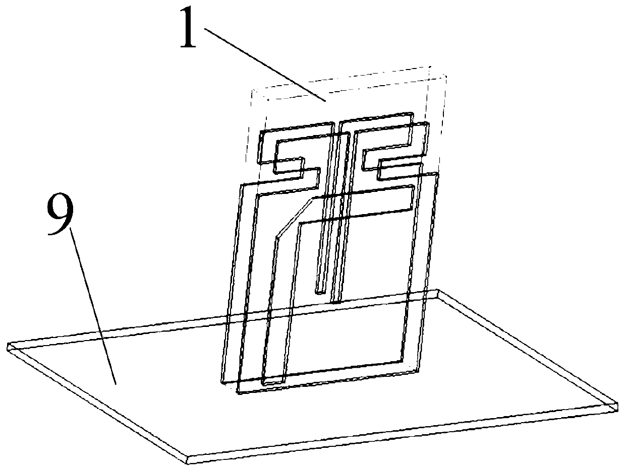
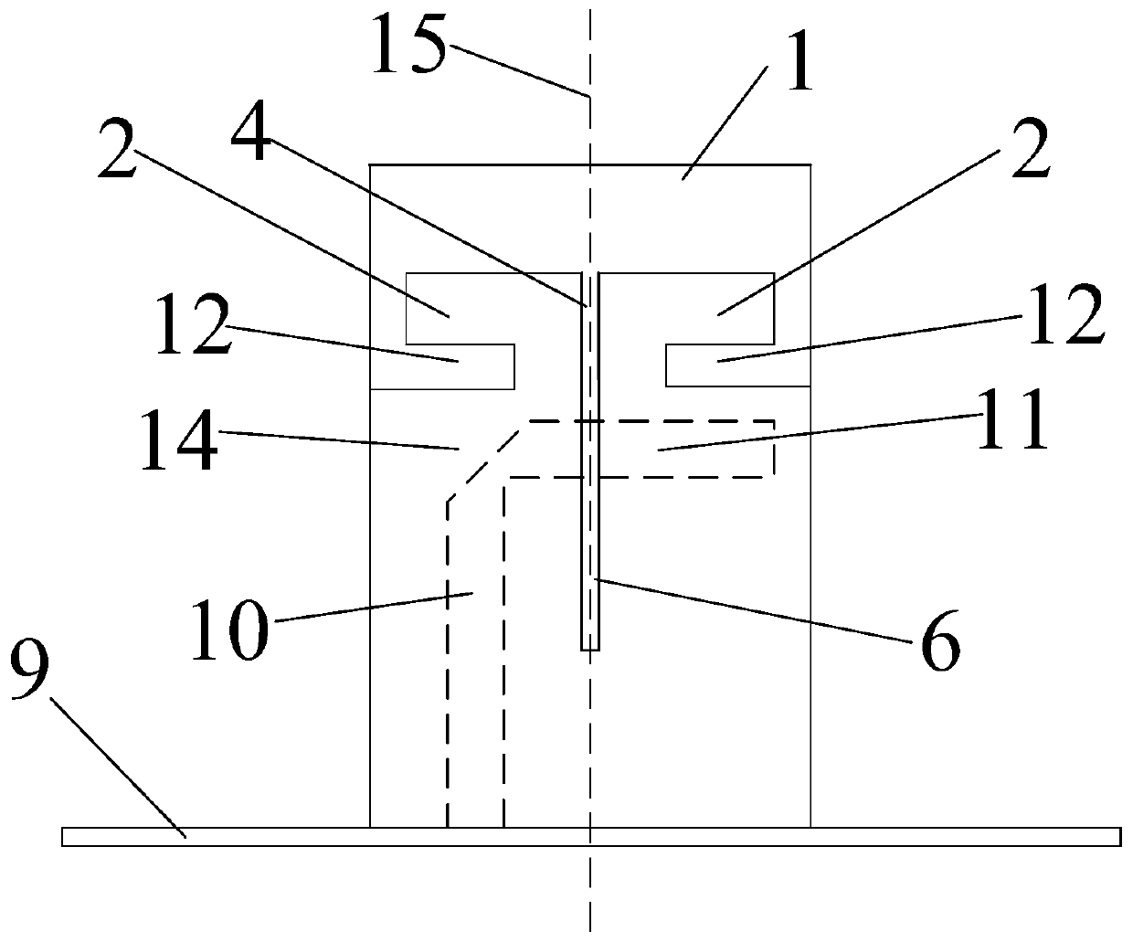
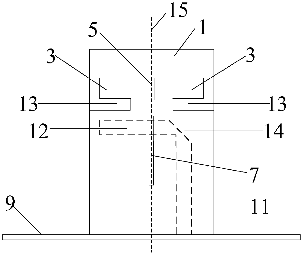
[0030] A millimeter-wave printed dipole antenna array radiating unit according to an embodiment of the present invention includes a dielectric substrate 1, a feeding stripline 8 and two dipole antennas, and the middle of the two radiating arms of the dipole antenna is The position is provided with a slit; each of the two board surfaces of the dielectric substrate 1 is printed with one dipole antenna, and the feeding stripline 8 is arranged in the dielectric substrate 1 and is located between the two The position between the dipole antennas is parallel to the surface of the dielectric substrate 1; the feeding stripline 8 intersects the projection of the slot at the lamination angle.

[0031] First of all, a dipole antenna is printed on each of the two board surfaces of the dielectric substrate 1, which enhances the radiation and reception capabilities of the dipole antenna. Secondly, due to the projection and gap of the feeding stripline 8 in the horizontal direction The projec...


PUM


Abstract

The invention relates to a millimeter wave printed dipole antenna array radiating element and an array antenna. The millimeter wave printed dipole antenna array radiating element include a dielectricsubstrate, a feed strip line, and a dipole antenna. First, two dipole antennas are printed on the two surfaces of the dielectric substrate respectively so as to enhance the radiating and receiving capabilities of the dipole antennas. Secondly, because the projection of the feed strip line in the horizontal direction and the projection of a slot in the horizontal direction intersect each other, theslot is divided into two sections, the upper section of which is a series feed slot, and the lower section of which is a balance/unbalance conversion structure. The series feed slot moves the radiating arms of the dipole antennas upward to facilitate feeding. The balance/unbalance conversion structure improves the working frequency band of the dipole antennas such that the dipole antennas can operate in a wide frequency band. Thus, the millimeter wave printed dipole antenna array radiating element that is convenient for feeding and can operate in a wide frequency band is achieved, and is simple in structure and easy to machine.

Description

technical field [0001] The invention relates to the technical field of dipole antennas, in particular to a millimeter-wave printed dipole antenna array radiation unit and an array antenna. Background technique [0002] As an important part of modern communication systems, antennas mainly function to receive and transmit electromagnetic waves. With the development of communication technology, the performance requirements of communication systems for antennas are also increasing. At present, the conventional printed dipole antenna is to print the dipole antenna on a thin layer of dielectric substrate, which has the advantages of light weight, small size, easy integration into arrays, etc., and has good bandwidth characteristics and high pole Purity. Its structure is that on the dielectric substrate perpendicular to the metal reflector, a dipole antenna is printed on one side, and a matching feeder is printed on the other side, but its frequency band is narrow, and the size of...

Claims


Application Information

Patent Timeline
IPC IPC(8): H01Q1/38H01Q1/50H01Q9/16H01Q13/10H01Q19/10H01Q21/00
CPCH01Q1/38H01Q1/50H01Q9/16H01Q13/10H01Q19/10H01Q21/00
Inventor 徐名一罗成斌
Owner BEIJING INST OF RADIO MEASUREMENT
Why Eureka
Try Eureka