
Rock sample grinding and separating device and method

A rock sample and separation device technology, applied in the field of petroleum geological experiments, can solve the problems of destroying the nature of shale itself, low experiment efficiency, and atmospheric environmental pollution, so as to reduce the hazards of dust pollution and debris, improve timeliness and accuracy, The effect of simplifying the experimental process

Active Publication Date: 2020-02-21
CHINA UNIV OF PETROLEUM (BEIJING)
View PDF13 Cites 3 Cited by
  • Summary
  • Abstract
  • Description
  • Claims
  • Application Information

AI Technical Summary

Problems solved by technology

However, the high content of silicon and calcium will lead to an increase in the hardness of shale rocks. In the process of grinding with existing methods and devices, insufficient grinding and large sample loss often occur, which is not conducive to the development of experiments.
[0009] 2. The existing methods and devices cannot combine the two processes of rock grinding and rock separation, and can only perform the two processes of grinding and screening separately. The required time and workload are relatively large, and the experimental efficiency is low.
[0010] 3. In the experimental process using existing methods and devices, if there is a long time interval between the two processes of grinding and screening, the ground shale powder will react with oxygen, water vapor and other substances in the atmosphere, and water absorption will occur Or suffer from oxidation, destroying the properties of shale itself, leading to deviations in subsequent experimental results
[0011] 4. Most of the existing rock sample acquisition technologies are open and without external equipment protection, so a large amount of dust and gravel will be generated during the grinding and screening process, which will cause physical damage to the experimenters and will also damage the air pollution

Method used

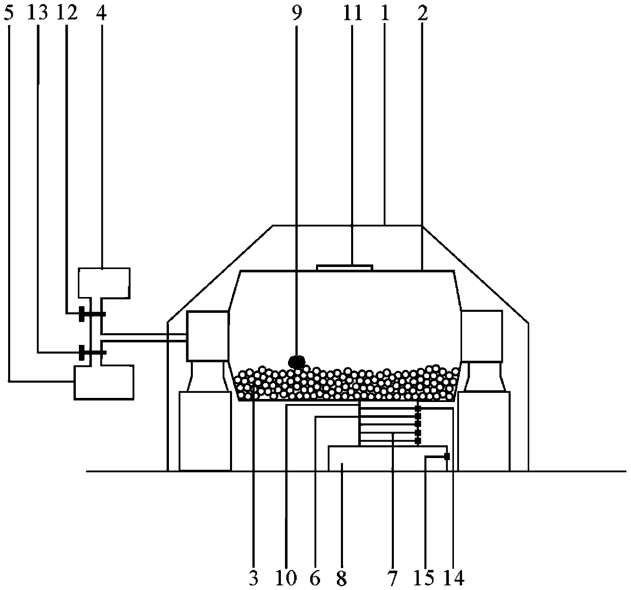
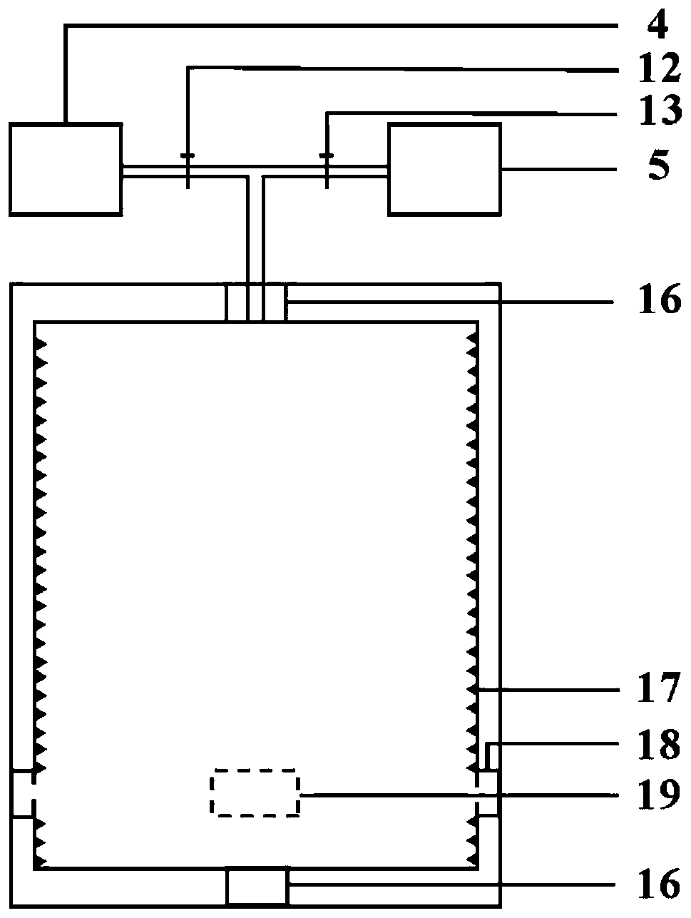
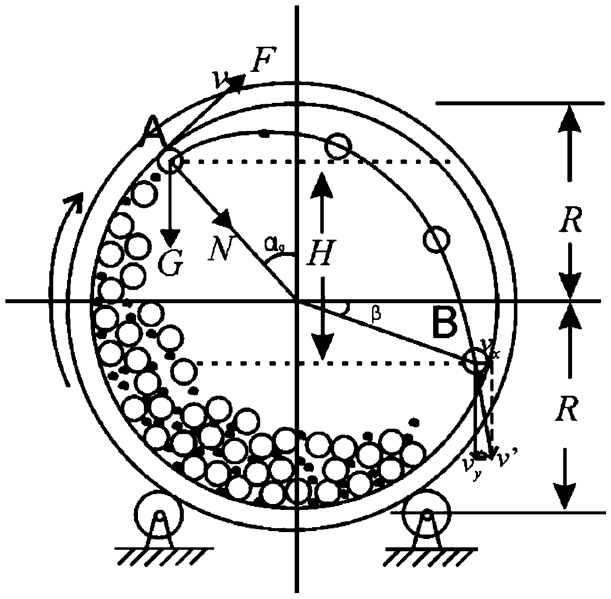

Image

  • Rock sample grinding and separating device and method
  • Rock sample grinding and separating device and method
  • Rock sample grinding and separating device and method

Examples


Embodiment Construction

[0036] The details of the present invention can be understood more clearly with reference to the accompanying drawings and the description of specific embodiments of the present invention. However, the specific embodiments of the present invention described here are only for the purpose of explaining the present invention, and should not be construed as limiting the present invention in any way. Under the teaching of the present invention, the skilled person can conceive any possible modification based on the present invention, and these should be regarded as belonging to the scope of the present invention. It should be noted that when an element is referred to as being “disposed on” another element, it may be directly on the other element or there may also be an intervening element. When an element is referred to as being "connected to" another element, it can be directly connected to the other element or intervening elements may also be present. The terms "mounted", "connec...


PUM

PropertyMeasurementUnit
Diameteraaaaaaaaaa

Abstract

The invention discloses a rock sample grinding and separating device and a method. The device comprises a shell, a gas device, a cleaning device and a rock separating system, wherein a grinding machine is arranged in the shell, the grinding machine comprises a body, abrasive particles are movably arranged in the body, a rotating shaft is arranged with the body, the body can rotate around a rotating shaft to drive the abrasive particles to grind a rock sample, a feeding port and a discharging port are arranged with the body, a feeding channel which can be opened and closed is formed between theshell and the feeding port, the gas device communicates with the body through a pipeline and is used for blowing gas to the rock sample of the body, the cleaning device communicates with the body through a pipeline and is used for supplying cleaning liquid to the body, and the rock separating system communicates with the discharging port, and the rock separating system comprises screens with different mesh numbers. According to the rock sample grinding and separating device and the method, the target rock sample can be efficiently, safely and controllably ground.

Description

technical field [0001] The invention relates to the technical field of petroleum geological experiments, in particular to a rock sample grinding and separating device and method. Background technique [0002] The statements in this section only provide background information related to the present disclosure and may not constitute prior art. [0003] Shale oil and gas are important unconventional oil and gas resources. At present, the exploration and development of shale oil and gas is in a state of rapid development. Shale oil and gas are mainly stored in the pores of shale reservoirs, and the degree of development of pores in shale reservoirs is the basic premise for shale to have good oil and gas bearing properties. For shale reservoirs, the storage space of oil and gas is mainly concentrated in pores below 1 μm. Conventional core description, thin section analysis and other methods cannot describe pores of this scale, and it is often necessary to use X-ray diffraction...

Claims


Application Information

Patent Timeline
IPC IPC(8): B02C17/10B02C17/18B02C17/20
CPCB02C17/10B02C17/18B02C17/184B02C17/1865B02C17/1875B02C17/20
Inventor 高之业薛子鑫姜振学范毓鹏王鑫熊书苓李慧玄麒祥成雨梁祝
Owner CHINA UNIV OF PETROLEUM (BEIJING)
Learn More