Variable-frequency wind supply device for rail transit vehicle

A technology for rail transit vehicles and air supply devices, which is applied to vehicle components, air treatment devices, transportation and packaging, etc. It can solve the problems of reduced air quality of compressed air, affecting the service life of adsorbents, and limited processing capacity of single-tower dryers. , to achieve the effect of meeting the requirements of advanced repair programs, improving versatility, and strong environmental adaptability

Active Publication Date: 2020-02-21
NANJING CRRC PUZHEN HAITAI BRAKE EQUIP CO LTD
View PDF8 Cites 2 Cited by
  • Summary
  • Abstract
  • Description
  • Claims
  • Application Information

AI Technical Summary

Problems solved by technology

The processing capacity of the single-tower dryer is limited, and it can only achieve backflush regeneration when the compressor is shut down, which cannot adapt to long-term continuous working conditions
[0011] When the double-tower dryer is directly used, the adsorption tower of the double-tower dryer is easy to enter a large amount of liquid water and oil, which directly affects the service life of the adsorbent. In the later stage of the maintenance process, the air quality of the compressed air drops significantly.
The double-tower dryers used in rail transit generally use molecular sieves as adsorbents. Due to the frequent start and stop of the compressor, the molecular sieves are subject to frequent airflow impacts, and are prone to produce tiny powder particles. It will have an adverse effect on the action performance and life of the rail transit vehicle and affect the safe operation of the rail transit vehicle.

Method used


Image

  • Variable-frequency wind supply device for rail transit vehicle
  • Variable-frequency wind supply device for rail transit vehicle
  • Variable-frequency wind supply device for rail transit vehicle

Examples


Embodiment Construction

[0043] The present invention will be described in detail below in conjunction with the accompanying drawings and specific embodiments.

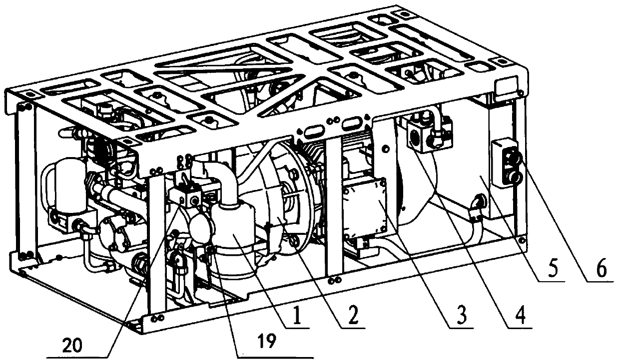
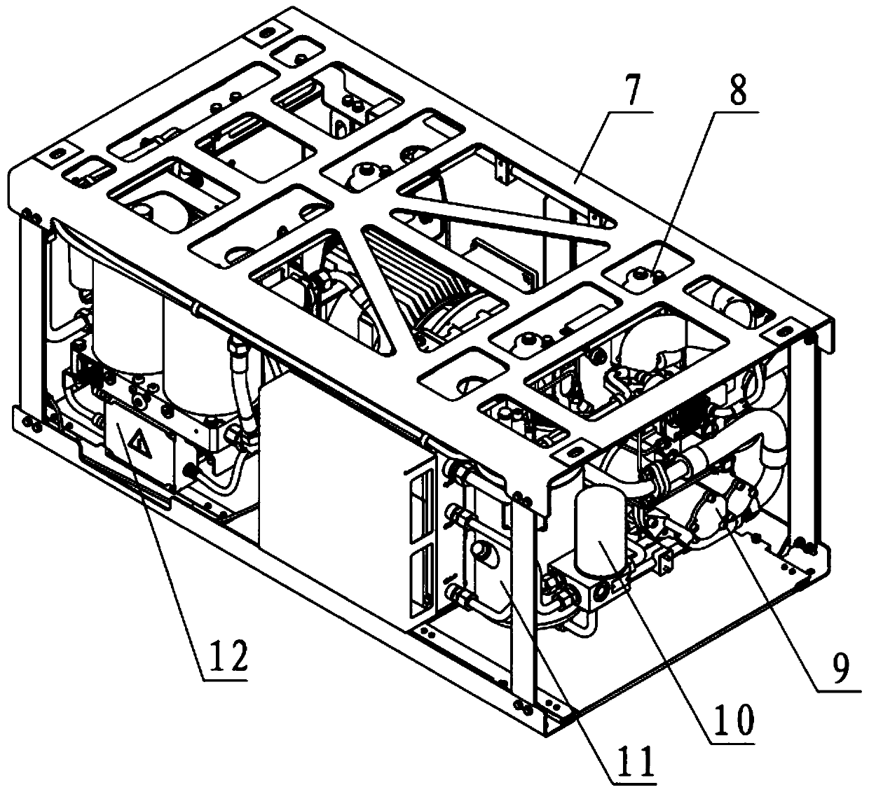
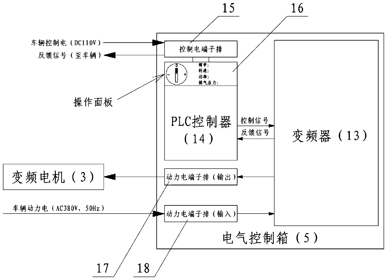
[0044] Such as figure 1 and 2 As shown, a frequency conversion air supply device for rail transit vehicles includes a hoisting frame 7, an electrical control box 5, an integrated air post-processing device 12, an outlet pressure maintaining valve 4, and a screw compressor. The screw compressor includes an air filter 1 , a screw host 9 , an oil-gas separation tank 11 , an oil filter 10 , an air cooling system 2 , and an inverter motor 3 . The hoisting frame 7 is installed on the bottom of the vehicle, and the screw compressor is connected with the hoisting frame 7 through an elastic shock absorber 8, which can prevent the vibration from being transmitted to the vehicle. The air supply device is electrically connected to the vehicle through the electrical connector 6 . The variable frequency motor 3 drives the screw host 9 and the air coolin...


PUM


Abstract

The invention discloses a variable-frequency wind supply device for a rail transit vehicle. The variable-frequency wind supply device comprises a hoisting frame, an electrical control box, an integrated air aftertreatment device, an outlet pressure maintenance valve and a screw compressor, wherein the screw compressor comprises an air filter, a screw main machine, an oil-gas separation tank, an oil filter, an air cooling system and a variable-frequency motor, the wind supply device is electrically connected with the vehicle through an electric connector, the variable-frequency motor drives thescrew main machine and the air cooling system, air is sucked through the air filter, the air is compressed by the screw main machine and then is subjected to oil-gas separation through the oil-gas separation tank, the compressed air is cooled by the air cooling system and then is subjected to filtering and drying treatment through the integrated air aftertreatment device, and finally clean and dry compressed air is output through an outlet pressure maintaining valve. According to the variable-frequency wind supply device, the wind demand of the rail transit 3 to 6 marshalling vehicles can beuniversally adapted, meanwhile, the phenomenon of lubricating oil emulsification is effectively prevented, and the application reliability of the whole life cycle of the wind supply device is guaranteed.

Description

technical field [0001] The invention relates to the braking technology of rail transit vehicles, in particular to a frequency conversion type air supply device for rail transit vehicles. Background technique [0002] The existing rail transit 3 to 6 marshalling vehicles usually use fixed-displacement air supply devices. Because the rail transit vehicle air supply devices are usually in a discontinuous working system, the operating rate of the air supply devices is generally 10% according to the operating conditions of the vehicles. ~80%, and the air volume of the same vehicle will vary in different stages of its life cycle. [0003] When the operation rate of the air supply device is low, each operation time is short, and the lubricating oil cannot quickly heat up to the pressure dew point of the compressed air. Every time the compressor is started, liquid water will be produced and cannot be effectively evaporated. After a long time, there will be Lubricating oil emulsific...

Claims


Application Information

Patent Timeline
Patent Type & Authority Applications(China)
IPC IPC(8): B61H11/06B60T17/00B01D53/26B01D46/00
CPCB61H11/06B60T17/002B60T17/004B01D53/261B01D2257/80B01D2258/06B01D46/56
Inventor 王红旗徐祥晖徐树亮牛瑞郭志刚章萍
Owner NANJING CRRC PUZHEN HAITAI BRAKE EQUIP CO LTD
Why Eureka
Try Eureka