Hydraulic-driving generator unit
A generator set, hydraulic drive technology, applied in the direction of hydropower, engine components, machines/engines, etc., can solve the problems of complex structure, low conversion efficiency, large volume, etc., to reduce volume, improve output speed and efficiency. Effect
- Summary
- Abstract
- Description
- Claims
- Application Information
AI Technical Summary
Problems solved by technology
Method used
Image

Examples
Embodiment 1
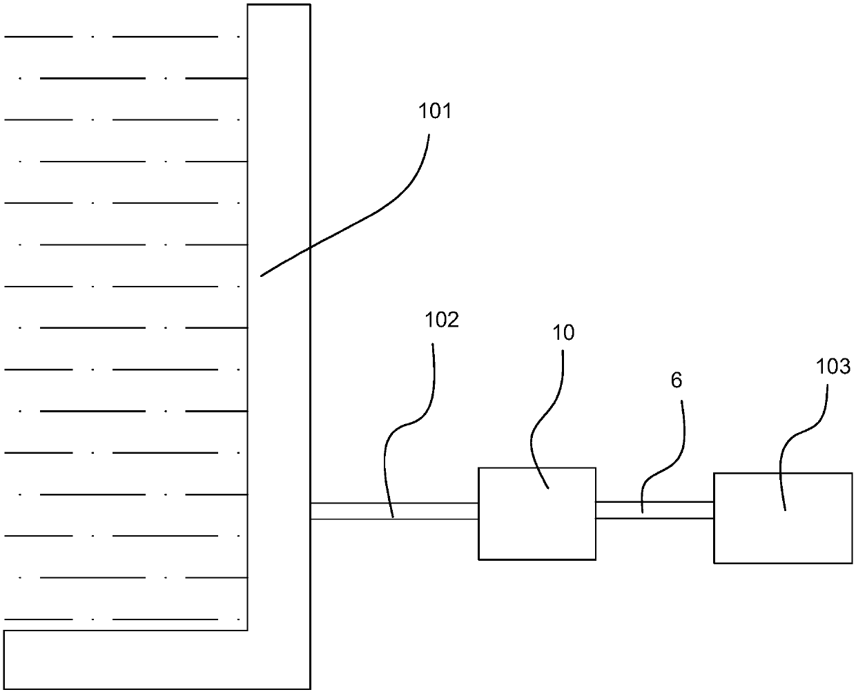
[0054] A kind of hydraulically driven generating set provided by this embodiment is arranged in a water source with a high water head, such as a reservoir power station, referring to figure 1 As shown, the hydraulically driven generator set is arranged downstream of the dam. The hydraulically driven generator set includes: a water diversion pipe 102, a hydraulic power unit 10 and a power generation assembly 103. The water diversion pipe 102 connects the high-pressure water source of the dam 101 to the hydraulic power unit 10, and the hydraulic power unit 10 Generate driving kinetic energy and drive and connect the power generation assembly 103 through the transmission mechanism 6 .
[0055]Wherein, the power generation assembly 103 is a conventional generator structure, including: a rotor shaft, a coil arranged on the rotor shaft, and a stator winding. The coil is energized to generate a magnetic field, and the rotation of the rotor shaft drives the coil to rotate to generate a...
Embodiment 2
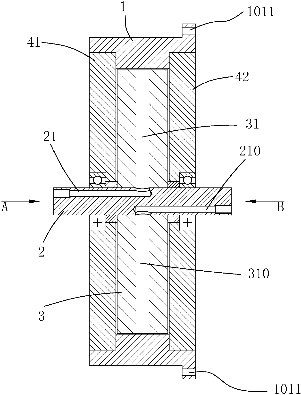
[0078] The water-driven generating set of this embodiment includes a hydraulic power unit and a power generation assembly. Compared with the first embodiment, the improvement lies in the hydraulic power unit. For details, please refer to Figure 8 to Figure 11 , the hydraulic power unit includes 2 independent working units to form a secondary drive structure, that is, the core body 3 is provided with 2 water flow channels along the circumference, and each water flow channel includes a liquid inlet channel 31 with a level above 1 and a secondary flushing channel 300. Arrange and discharge flow channels along the circumference of the core body 3 . The hydraulic power device includes an outer ring 1, a plurality of driving recesses 11 are arranged on the inner ring surface of the outer ring; 2 groups of nozzles, outlets, and at least one flushing channel between each group of nozzles and outlets; 2 liquid inlet channels 31, 32 are provided on the core, which correspond to the con...
Embodiment 3
[0081] The hydraulic drive generator set of this embodiment includes a hydraulic power unit and a power generation assembly. Compared with Embodiment 1, the improvement lies in the hydraulic power unit. The hydraulic power unit of this embodiment includes 4 or more independent work units to form Multi-stage driving structure, 3 or more water flow channels are arranged on the core body along the circumference, each water flow channel includes a liquid inlet channel and a secondary flush flow channel of more than one level, and is arranged along the core body circumferential direction and discharge flow channels , the liquid inlet channel and the liquid discharge channel are arranged on the mating surfaces of the left and right cores. The shaft is provided with a number of liquid inlet shafts and liquid outlet shafts corresponding to the water flow channel. The water flow enters from the liquid inlet shaft of the shaft, and is sprayed out through the core liquid inlet channel to ...
PUM
 Abstract
Description
Claims
Application Information
 - R&D
- Intellectual Property
- Life Sciences
- Materials
- Tech Scout
- Unparalleled Data Quality
- Higher Quality Content
- 60% Fewer Hallucinations
Browse by: Latest US Patents, China's latest patents, Technical Efficacy Thesaurus, Application Domain, Technology Topic, Popular Technical Reports.
© 2025 PatSnap. All rights reserved.Legal|Privacy policy|Modern Slavery Act Transparency Statement|Sitemap|About US| Contact US: help@patsnap.com