
Tracked peanut seedling film removing and rolling-cutting combine machine

A peanut seedling and crawler-type technology, which is applied in the field of crawler-type peanut seedling combined film removal kneading and cutting machine, can solve the problems of cumbersomeness, small working space, and low work efficiency, and achieve high degree of automation, small turning radius, and high work efficiency Effect

Pending Publication Date: 2020-02-28
日照市勇杰农业装备有限公司
View PDF0 Cites 0 Cited by
  • Summary
  • Abstract
  • Description
  • Claims
  • Application Information

AI Technical Summary

Problems solved by technology

At present, most of the film-removing kneading and cutting machines work in fixed positions. When peanuts are harvested, peanut seedlings need to be collected and then transported to designated locations for chopping. This method is cumbersome and increases the workload of farmers.
At present, most self-propelled peanut seedling film removal kneading and cutting machines are wheeled structures. For wheeled peanut seedling film removal kneading and cutting machines, due to the high height of the wheels, the fuselage is located between the wheels on both sides, so the width of the fuselage Restricted, the internal space of the fuselage is restricted
The working space inside the fuselage is small, and its work efficiency is relatively low
The wheel structure has a small contact area with the ground, and it is easy to sink when working on a soft bottom or on the ground after rain

Method used


Image

  • Tracked peanut seedling film removing and rolling-cutting combine machine
  • Tracked peanut seedling film removing and rolling-cutting combine machine
  • Tracked peanut seedling film removing and rolling-cutting combine machine

Examples


Embodiment 2

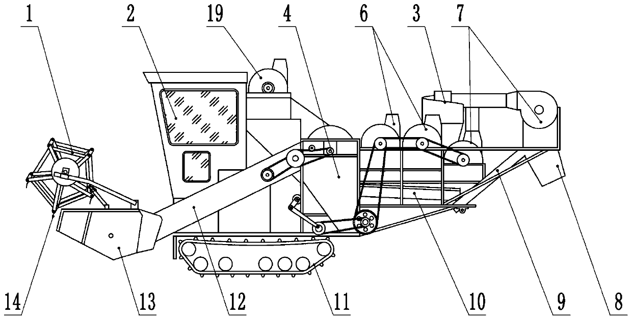
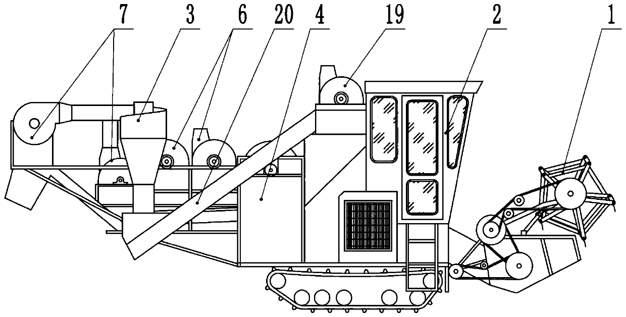
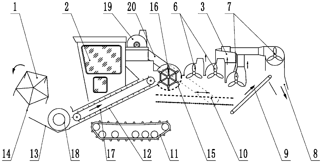
[0032] The feeding device described in Embodiment 2 is the feeding conveyor belt 20 . The vibrating screen 10 has a two-layer structure, with large holes in the upper layer and small holes in the lower layer. Bulk peanut seedlings are left on the vibrating screen 10 upper floors, and small pieces of peanut seedlings fall on the vibrating screen 10 lower floors. The discharge conveyor belt 9 is located below the rear end of the lower layer of the fuselage 10, and the qualified crushed peanut seedlings after the lower layer of the vibrating screen 10 fall on the discharge conveyor belt 9 to be output. The return conveyor belt 20 is located on one side of the fuselage 4 , the head end of the return conveyor belt 20 is located at the vibrating screen 10 , and the end of the return conveyor belt 20 is located above the front end of the fuselage 4 . The two ends of the return conveyor belt 20 are respectively provided with a material conveying device, and the material conveying dev...


PUM


Abstract

The invention belongs to the field of agricultural machinery and discloses a tracked peanut seedling film removing and rolling-cutting combine machine. The combine machine is characterized by comprising a vehicle body, a pickup platform, a bridge body, a machine body, fans, a cutting roller, a vibrating screen and a return pipeline. The vehicle body comprises a chassis, an engine, a cab, a traveling device, a control system, a hydraulic system and a power output system. The pickup platform is in a shell structure with the front upper portion open and is provided with a pickup roller and a screw. The cutting roller is arranged at an opening of the inner front end of a cavity of the machine body, and the vibrating screen is arranged under a mesh screen which is arranged under the cutting roller. The fans are positioned on a route of peanut seedlings and include a high-suction fan and a low-suction fan. A cyclone dust collector is arranged above the front end of the machine body, an air outlet of the high-suction fan is connected with the cyclone dust collector through the return pipeline, an opening of the lower end of the cyclone dust collector is communicated with the cavity of themachine body, and the traveling device is in a tracked structure. Compared with the prior art, the tracked peanut seedling film removing and rolling-cutting combine machine has advantages of high automation degree and high efficiency.

Description

technical field [0001] The invention relates to an agricultural machine, in particular to a crawler-type peanut seedling combined film-removing kneading and cutting machine. Background technique [0002] The film removal kneading and cutting machine is used to chop peanut seedlings and remove the plastic film in them, which is used to feed livestock such as cattle and sheep. At present, most of the film-removing kneading and cutting machines work in fixed positions. When peanuts are harvested, peanut seedlings need to be collected and then transported to designated locations for chopping. This method is cumbersome and increases the workload of farmers. At present, most self-propelled peanut seedling film removal kneading and cutting machines are wheeled structures. For wheeled peanut seedling film removal kneading and cutting machines, due to the high height of the wheels, the fuselage is located between the wheels on both sides, so the width of the fuselage Restricted, the...

Claims


Application Information

Patent Timeline
Patent Type & Authority Applications(China)
IPC IPC(8): A01F29/06A01F29/09A01D89/00B04C9/00B07B1/28B07B1/46
CPCA01D89/001A01F29/06A01F29/09B04C9/00B07B1/28B07B1/4609
Inventor 赵福勇赵世杰
Owner 日照市勇杰农业装备有限公司
Learn More