Energy-saving quenching launder

An energy-saving, trough technology, applied in quenching devices, heat treatment equipment, manufacturing tools, etc., can solve problems such as the inability to meet the requirements of the quenching flow rate of the piston rod, quenching deformation, etc., and achieve obvious energy-saving effect, cost saving, power configuration small effect

Pending Publication Date: 2020-02-28
溧阳市永恒热处理有限公司
View PDF3 Cites 1 Cited by
  • Summary
  • Abstract
  • Description
  • Claims
  • Application Information

AI Technical Summary

Problems solved by technology

[0004] However, the quenching devices disclosed in Chinese patents such as CN209537564U, CN201517120U, and CN105506241A cannot be applied to piston rods with larger diameters and longer lengths, and other domestic piston rod quenching requirements are not as high as the above-mentioned requirements, so there is no Proprietary quenching equipment, and the conventional method is to hoist the piston rod horizontally and immerse it in the quenching tank, which will inevitably fail to meet the requirements of the quenching flow rate on the surface of the piston rod, and at the same time, the overall quenching of the piston rod is also prone to quenching deformation

Method used


Image

  • Energy-saving quenching launder
  • Energy-saving quenching launder
  • Energy-saving quenching launder

Examples


Embodiment Construction

[0032] The present invention will be described in further detail below in conjunction with the accompanying drawings.

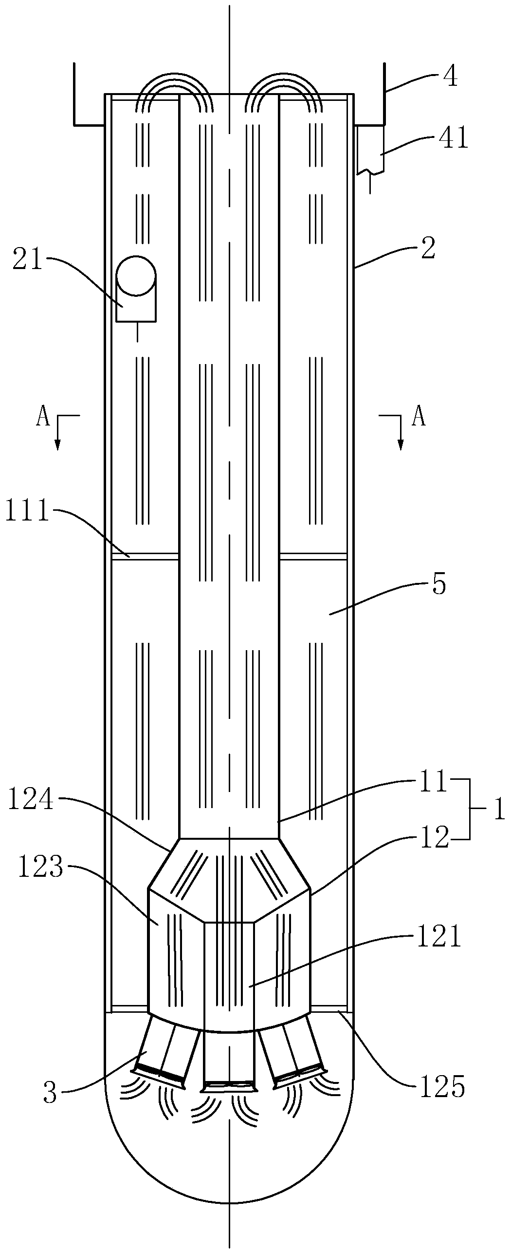
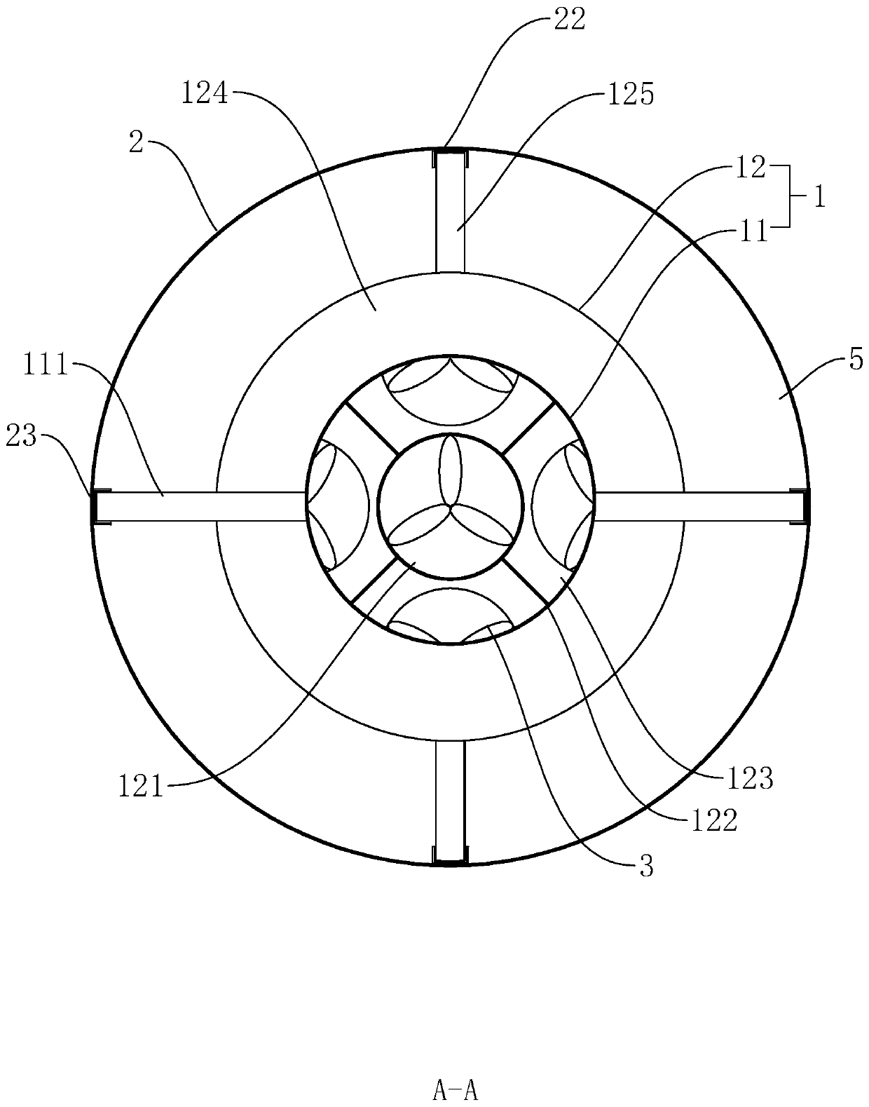
[0033] Such as figure 1 As shown, it is an energy-saving quenching launder disclosed by the present invention, which includes a quenching inner cylinder 1 and an outer cylinder 2 installed coaxially inside and outside. The quenching inner cylinder 1 includes a quenching working area 11 connected up and down and a dynamic pressure energy storage In the area 12, the inner side wall of the installation outer cylinder 2 is symmetrically provided with the installation groove 22 and the positioning groove 23 along its axial direction, and the side walls located in the dynamic pressure energy storage area 12 and the quenching work area 11 are respectively symmetrically fixed with installation grooves along their respective axial directions. The axis of the rod 125 and the positioning rod 111 , and the mounting rod 125 and the positioning rod 111 are perpendicular t...


PUM

PropertyMeasurementUnit
lengthaaaaaaaaaa
diameteraaaaaaaaaa
lengthaaaaaaaaaa

Abstract

The invention discloses an energy-saving quenching launder, and belongs to the field of heat treatment equipment. The energy-saving quenching launder comprises a quenching inner cylinder and an installation outer cylinder which are relatively fixed and coaxially arranged, the quenching inner cylinder comprises a quenching working area and a dynamic pressure energy storage area which communicate with each other up and down, the cross-sectional area of the quenching working area is the same in the length direction of the quenching working area, a power device is arranged on the side, towards thecylinder bottom of the installation outer cylinder, of the dynamic pressure energy storage area, a cooling medium inlet pipe is arranged on the side wall of the installation outer cylinder, an overflow groove is formed in an opening of the installation outer cylinder, and a hot medium outlet pipe is arranged in the overflow groove; and an internal circulation area is formed between the quenchinginner cylinder and the installation outer cylinder, and a cooling medium and a quenching medium sequentially pass through the bottom of the internal circulation area, the power device, the dynamic pressure energy storage area, the quenching working area and the top of the internal circulation area to form a circulation line. According to the energy-saving quenching launder, relevant principles ofhydrodynamics are fully utilized, various energy losses caused by eddy flow, turbulent flow, internal friction and the like of liquid are fully considered, conversion of kinetic and potential energy is fully utilized, the situation that the requirements of product processing are met by the flow rate of a working medium through application performance, and meanwhile the energy-saving effect is alsovery obvious.

Description

technical field [0001] The invention relates to the technical field of heat treatment equipment, in particular to an energy-saving quenching launder. Background technique [0002] Quenching is a heat treatment process in which steel is heated above the critical temperature, held for a certain period of time, and then cooled at a rate greater than the critical cooling rate to obtain uniform martensite. The purpose is to make the supercooled austenite undergo martensite Transformation into martensite or bainite, and then combined with tempering at different temperatures, according to the mechanical performance requirements of different parts, to greatly improve the rigidity, hardness, wear resistance, fatigue strength and Toughness and other mechanical properties, so as to meet the different requirements of various mechanical parts and tools. [0003] For example, in the prior art, the large-scale excavator cylinder piston rod produced by U.S. Caterpillar is as image 3 As sh...

Claims


Application Information

Patent Timeline
Patent Type & Authority Applications(China)
IPC IPC(8): C21D1/64
CPCC21D1/64
Inventor 赵小琴蒋勇南张育埝
Owner 溧阳市永恒热处理有限公司
Why Eureka
Try Eureka