
Profile steel-concrete composite beam hogging moment area structure based on high-performance material

A high-performance concrete, negative bending moment zone technology, applied in bridge materials, bridges, bridge parts, etc., can solve the problems of increasing the mid-span deflection of the main beam, corroding the steel beam, reducing the bending stiffness of the main beam, etc., and improving the quality of the bridge. and construction level, improve operational status, and broaden the scope of application

Pending Publication Date: 2020-02-28
LIAONING PROVINCIAL TRANSPORTATION PLANNING & DESIGN INST
View PDF8 Cites 8 Cited by
  • Summary
  • Abstract
  • Description
  • Claims
  • Application Information

AI Technical Summary

Problems solved by technology

[0003] Due to the deformation caused by the rotation and expansion of the beam body, the staggered deformation caused by the asynchronous elastic compression of the adjacent bridge hole supports, the negative bending moment of the fulcrum, repeated loads, local wheel loads of large transport vehicles, and temperature effects, etc., It is easy to cause problems such as cracking in the negative moment section shortly after the bridge is put into operation, reducing the bending stiffness of the main girder, increasing the mid-span deflection of the main girder, and causing corrosion of the steel girder due to cracking and water seepage, thus affecting the working performance and durability of the bridge. have very adverse effects
For steel-concrete composite girder bridges, due to the influence of steel-concrete interaction and the performance of connecting structures, the mechanical behavior of the structure in the negative moment zone is more complicated, which hinders the popularization and application of such bridges in engineering

Method used


Image

  • Profile steel-concrete composite beam hogging moment area structure based on high-performance material
  • Profile steel-concrete composite beam hogging moment area structure based on high-performance material
  • Profile steel-concrete composite beam hogging moment area structure based on high-performance material

Examples


Embodiment Construction

[0043] The following will clearly and completely describe the technical solutions in the embodiments of the present invention with reference to the accompanying drawings in the embodiments of the present invention. Obviously, the described embodiments are only some, not all, embodiments of the present invention. Based on the embodiments of the present invention, all other embodiments obtained by persons of ordinary skill in the art without making creative efforts belong to the protection scope of the present invention.

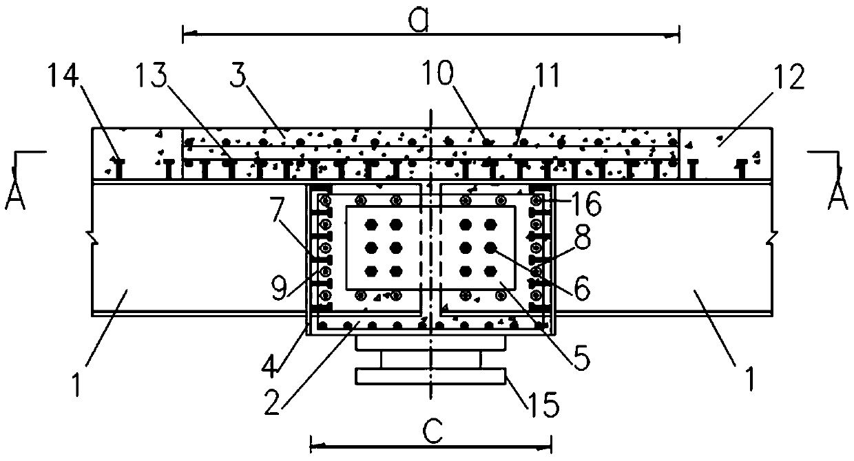
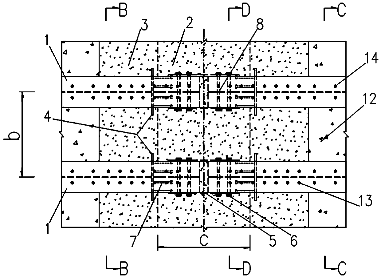
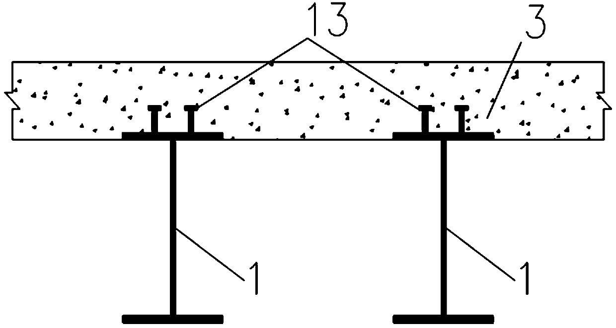
[0044] see Figure 1 to Figure 5 , the present invention provides a technical solution:

[0045] A steel-concrete composite beam negative moment zone structure based on high-performance materials, including:

[0046] Steel girder 1, the two adjacent butt joints at the ends of the steel girders are connected by connecting steel plates 5 and bolts 6, and the butt joints are called negative bending moment areas;

[0047] Reinforced concrete beam 2, the reinforc...


PUM


Abstract

The invention discloses a profile steel-concrete composite beam hogging moment area structure based on a high-performance material. The structure comprises steel beams, and reinforced concrete cross beams, wherein the two adjacent butt joint positions of the end parts of the steel beams are connected by adopting connecting steel plates and bolts, and the butt joint positions are referred to as hogging moment areas; and the reinforced concrete cross beams are fixed outside the hogging moment areas in a wrapping mode, the structure further comprises high-performance concrete bridge deck slabs; the high-performance concrete bridge deck slabs are laid directly above the hogging moment areas, specially, the high-performance concrete bridge deck slabs are laid on the top surfaces of the steel beams located in the hogging moment areas and are laid on the top surfaces of the reinforced concrete cross beams located in the hogging moment areas, and the high-performance concrete bridge deck slabsensure that the hogging moment areas are completely covered. The structure has the advantages of reducing the bearing bending moment of a main beam span, reducing the requirements of the structure onthe profile steel specification, saving the material consumption, widening the span diameter range of a bridge, improving the structural rigidity and being good in integrity, high in overload capacity, high in safety and the like.

Description

technical field [0001] The invention relates to the technical field of steel-concrete composite structure bridges, in particular to a steel-concrete composite beam negative moment region structure based on high-performance materials. Background technique [0002] At present, my country is in the context of vigorously promoting the steel structure industry. The all-steel structure is very beneficial in industrialization, but it is not economical to apply it to the construction of small and medium-span bridges. The steel-concrete composite structure has high bearing capacity, strong durability, and is convenient for industrialization of production, low construction cost, fast construction, and at the same time solves the problem of steel overcapacity. A lot of experience at home and abroad shows that the steel-concrete composite structure has become an important development direction of industrialization in the field of highway transportation. In particular, the profile steel...

Claims


Application Information

Patent Timeline
IPC IPC(8): E01D19/00E01D19/12E01D101/30E01D101/26
CPCE01D19/00E01D19/125E01D2101/26E01D2101/30
Inventor 鲁薇薇张冠华吴宪锴周丹韩基刚宋承哲李文全郭东升陈建荣商东洋王超王凯全志强
Owner LIAONING PROVINCIAL TRANSPORTATION PLANNING & DESIGN INST
Learn More