Working condition simulation test circuit and method for cascaded converter sub-module

A technology for simulating working conditions and testing circuits. It is applied in the direction of measuring electricity and parts and instruments of electrical measuring instruments. It can solve the problems of a large number of sub-modules, high safety requirements, and large system capacity, so as to save testing costs. Effect

Active Publication Date: 2020-02-28
SHANGHAI JIAO TONG UNIV
View PDF5 Cites 10 Cited by
  • Summary
  • Abstract
  • Description
  • Claims
  • Application Information

AI Technical Summary

Problems solved by technology

[0010] In view of the problems existing in the above-mentioned prior art, the present invention proposes a working condition simulation test circuit and method of cascaded converter sub-modules, using the auxiliary bridge arm and its corresponding control method, when the sub-module to be tested is cut off, the The auxiliary bridge arm is put into use to compensate for the voltage difference generated when the sub-module to be tested is cut off, and the auxiliary bridge arm is cut off when the sub-module to be tested is put into use, which solves the problem of applying correct voltage and current stress to the sub-module in the traditional method, while testing The system has a large system capacity, a large number of sub-modules, inflexible configuration, and high security requirements during testing.

Method used


Image

  • Working condition simulation test circuit and method for cascaded converter sub-module
  • Working condition simulation test circuit and method for cascaded converter sub-module
  • Working condition simulation test circuit and method for cascaded converter sub-module

Examples


Embodiment Construction

[0053] The present invention will be described in detail below in conjunction with specific embodiments. The following examples will help those skilled in the art to further understand the present invention, but do not limit the present invention in any form. It should be noted that those skilled in the art can make several modifications and improvements without departing from the concept of the present invention. These all belong to the protection scope of the present invention.

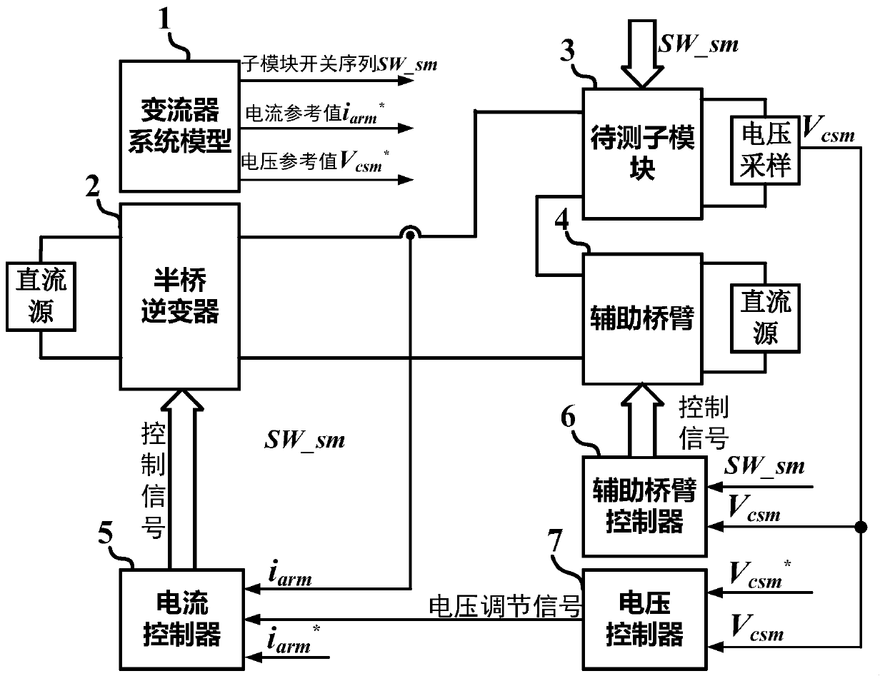
[0054] Such as figure 1 Shown is a schematic structural diagram of a working condition simulation test circuit of a cascaded converter sub-module according to an embodiment of the present invention.

[0055] Please refer to figure 1 , the operating condition simulation test circuit of the cascaded converter sub-module of this embodiment includes:

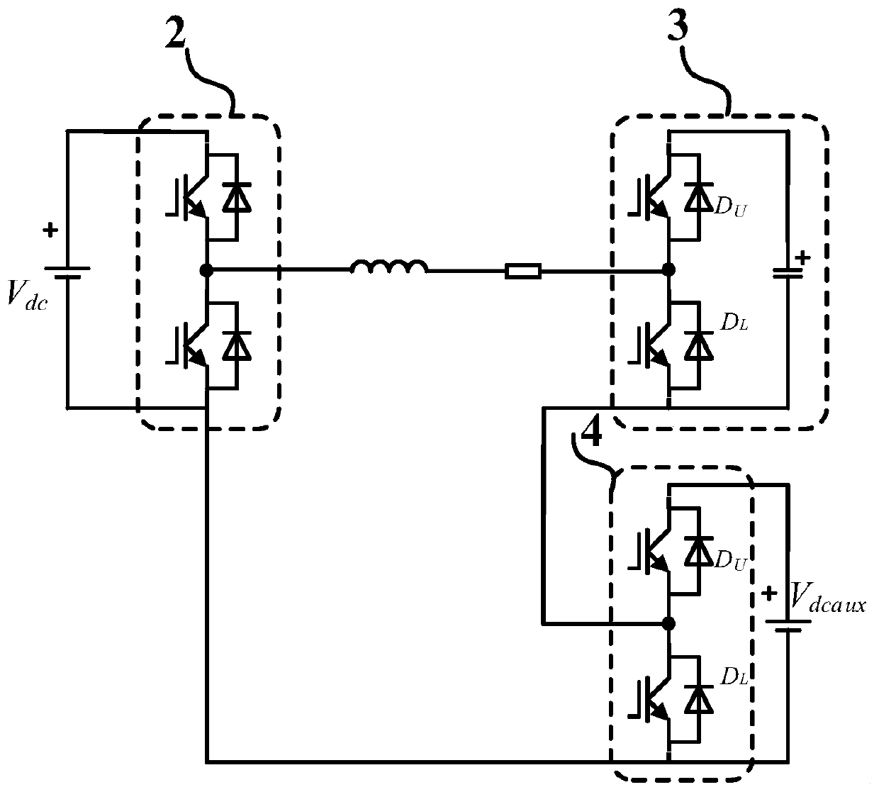
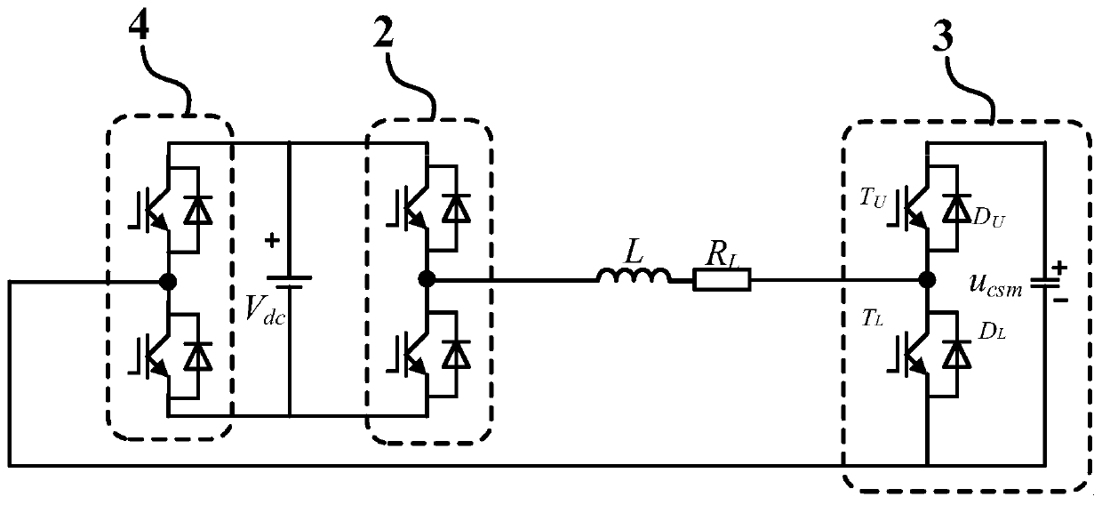
[0056] The current generator 2 is used to output current.

[0057] The sub-module 3 to be tested is used to receive the current generated by the cur...


PUM


Abstract

The invention discloses a working condition simulation test circuit and method for a cascaded converter sub-module. The circuit comprises a current generator which is used for generating a current needed by a to-be-tested sub-module; the to-be-tested sub-module which is used for receiving a current signal and outputting a capacitor voltage signal; a voltage controller which is used for receiving the capacitor voltage signal and generating a voltage regulation signal, so that the capacitor voltage of the to-be-tested sub-module is consistent with a reference voltage; a current controller whichis used for receiving the current signal and the voltage regulation signal and generating a control signal of the current generator to control the running state of the current generator; an auxiliarybridge arm which is switched on when the to-be-tested sub-module operates in a cut-off state and matches the current generator to carry out auxiliary adjustment on the output current of the current generator; an auxiliary bridge arm controller which is used for controlling the auxiliary bridge arm; and a converter system model which is used for controlling the to-be-tested sub-module, the currentcontroller and the voltage controller. According to the invention, the test cost is reduced, and the safety is improved.

Description

technical field [0001] The invention relates to the technical field of power electronics, in particular to a working condition simulation test circuit and method of a sub-module of a cascaded converter. Background technique [0002] In recent years, due to its scalability, cascaded converters have been widely used and paid attention to in medium-high voltage and high-power fields. However, with the continuous improvement of the voltage level and capacity of the cascaded converter, the number of sub-modules of the cascaded converter will also become very large, and the reliability of the cascaded converter mainly depends on the sub-modules of the cascaded converter. module reliability. In order to ensure the reliable operation of the cascaded converter system, the verification and testing of its sub-modules becomes very important. [0003] At present, the main modulation method of cascaded converters is nearest level approximation modulation. The operating conditions of cas...

Claims


Application Information

Patent Timeline
Patent Type & Authority Applications(China)
IPC IPC(8): G01R31/00G01R1/30
CPCG01R1/30G01R31/00
Inventor 马柯杨云霄
Owner SHANGHAI JIAO TONG UNIV
Why Eureka
Try Eureka