Motor core manufacturing equipment and manufacturing method
A technology for manufacturing equipment and iron cores, which is applied to the manufacturing equipment of motor iron cores and its manufacturing field, which can solve the problems of low cutting efficiency, difficulty in direct cutting, tearing, etc., to improve cutting efficiency, reduce processing costs, and improve processing efficiency Effect
- Summary
- Abstract
- Description
- Claims
- Application Information
AI Technical Summary
Problems solved by technology
Method used
Image

Examples
Embodiment 1
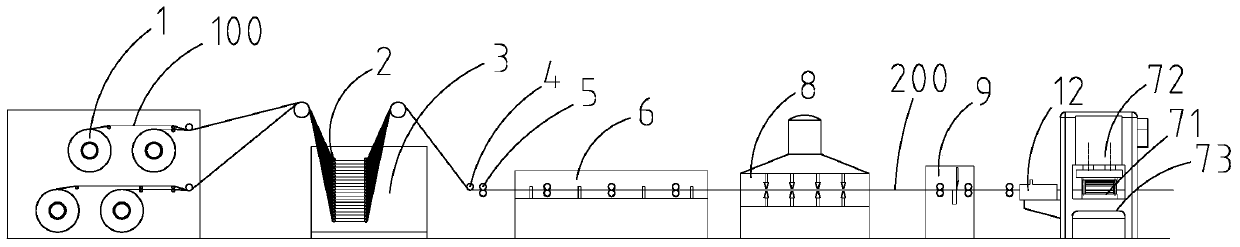
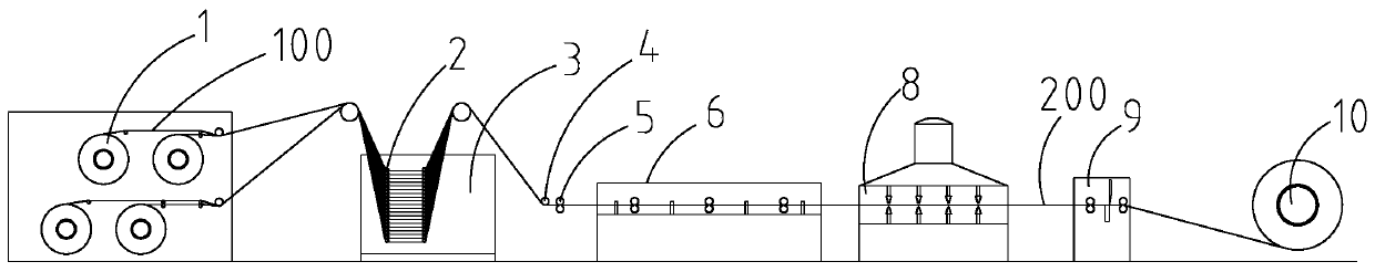
[0059] Such as figure 1 , 2 , Shown in 3, a kind of manufacturing equipment of motor iron core, it comprises:
[0060] A cladding sheet cladding device for cladding at least two layers of ultra-thin strips 100 into a cladding sheet 200;
[0061] cutting means for cutting the clad panel 200 to obtain panels;
[0062] A dispensing mechanism for spraying glue on the surface of a board sheet so that adjacent board sheets are bonded together.
[0063] In this embodiment, the glue sprayed by the glue dispensing mechanism is pressure sensitive glue. The ultra-thin strip 100 is an amorphous strip with a thickness of 0.01-0.15 mm or an ultra-thin silicon steel sheet with a thickness of 0.01-0.15 mm or other iron core materials with a thickness of 0.01-0.15 mm. The thickness of the clad sheet 200 is 0.1-1 mm.
[0064] Such as figure 1 , 2 As shown, the cladding device for cladding includes an unwinding device, a material distribution mechanism 2, a gluing mechanism 3, a laminatin...
Embodiment 2
[0085] The iron-based ultra-thin sheet material of 0.025±0.005mm thick amorphous or nanocrystalline strip is laminated into a 0.5mm thick clad plate 200 to make the motor iron core.
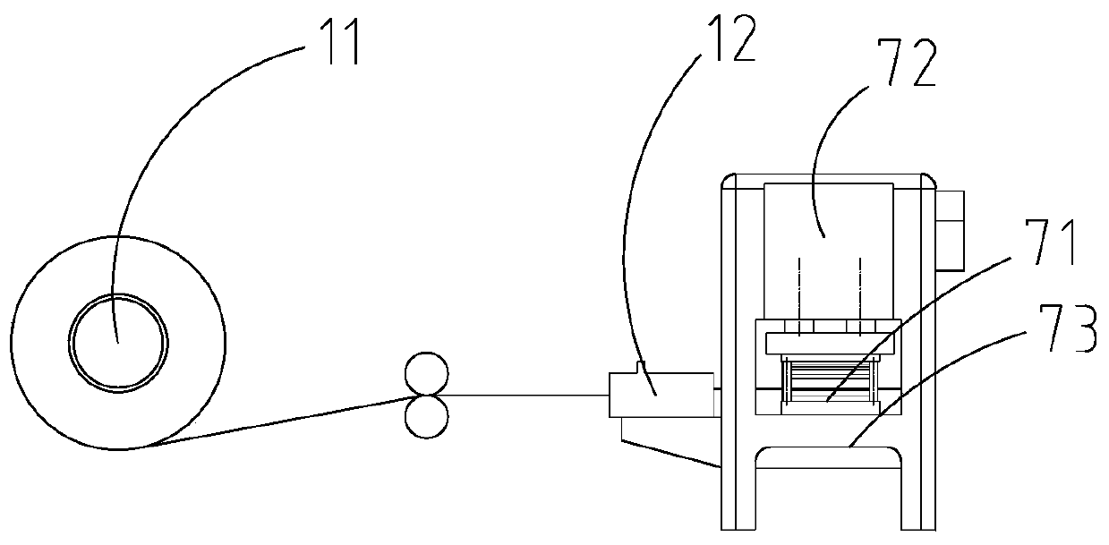
[0086] A normal 0.5mm non-oriented silicon steel sheet punching machine is used, and the precision of the supporting mold and the matching punching gap of the upper and lower molds are set according to the needs. Among them, the upper mold 72 has a special glue dispensing mechanism for gluing and lamination between layers.
[0087] Step 1: Select 4 rolls of 100 rolls of ultra-thin strips with a thickness of 0.025mm, each roll is made of 5 layers of ultra-thin strips 100, and place 100 rolls of ultra-thin strips on the feeding mechanism 1 , pull out the tape head, respectively pass 20 layers of ultra-thin strips 100 through the distributing roller frame of the material distributing mechanism 2, so that the ultra-thin strips 100 are evenly and regularly divided into 20 layers that are parallel up an...
Embodiment 3
[0098] The iron-based ultra-thin sheet material of 0.02±0.005 mm thick amorphous or nanocrystalline strip is laminated into a 0.2 mm thick clad plate 200 to make the motor iron core.
[0099] A normal 0.2mm non-oriented silicon steel sheet punching machine is used, and the precision of the supporting mold and the matching punching gap of the upper and lower molds are set according to the needs. Among them, the upper mold 72 has a special glue dispensing mechanism for gluing and lamination between layers.
[0100] Step 1: Select 100 rolls of 0.02mm thick ultra-thin strips and 2 rolls, each roll is made of 5 layers of ultra-thin strips 100, and place 100 rolls of ultra-thin strips on the feeding mechanism 1 , pull out the tape head, respectively pass 10 layers of ultra-thin strips 100 through the distributing roller frame of the material distributing mechanism 2, so that the ultra-thin strips 100 are evenly and regularly divided into 10 layers that are parallel up and down;
[0...
PUM
| Property | Measurement | Unit |
|---|---|---|
| thickness | aaaaa | aaaaa |
| thickness | aaaaa | aaaaa |
Abstract
Description
Claims
Application Information
 - R&D
- Intellectual Property
- Life Sciences
- Materials
- Tech Scout
- Unparalleled Data Quality
- Higher Quality Content
- 60% Fewer Hallucinations
Browse by: Latest US Patents, China's latest patents, Technical Efficacy Thesaurus, Application Domain, Technology Topic, Popular Technical Reports.
© 2025 PatSnap. All rights reserved.Legal|Privacy policy|Modern Slavery Act Transparency Statement|Sitemap|About US| Contact US: help@patsnap.com