Laser welding method combining ultrasonic welding with chilling

A laser welding and ultrasonic technology, applied in the direction of laser welding equipment, welding equipment, metal processing equipment, etc., to achieve a wide range of welding size, reduce stress concentration, and improve the effect of microhardness

Active Publication Date: 2020-03-06
DALIAN UNIV OF TECH
View PDF16 Cites 11 Cited by
  • Summary
  • Abstract
  • Description
  • Claims
  • Application Information

AI Technical Summary

Problems solved by technology

However, the adverse effect of this method on lateral shrinkage

Method used


Image

  • Laser welding method combining ultrasonic welding with chilling
  • Laser welding method combining ultrasonic welding with chilling

Examples


specific Embodiment approach

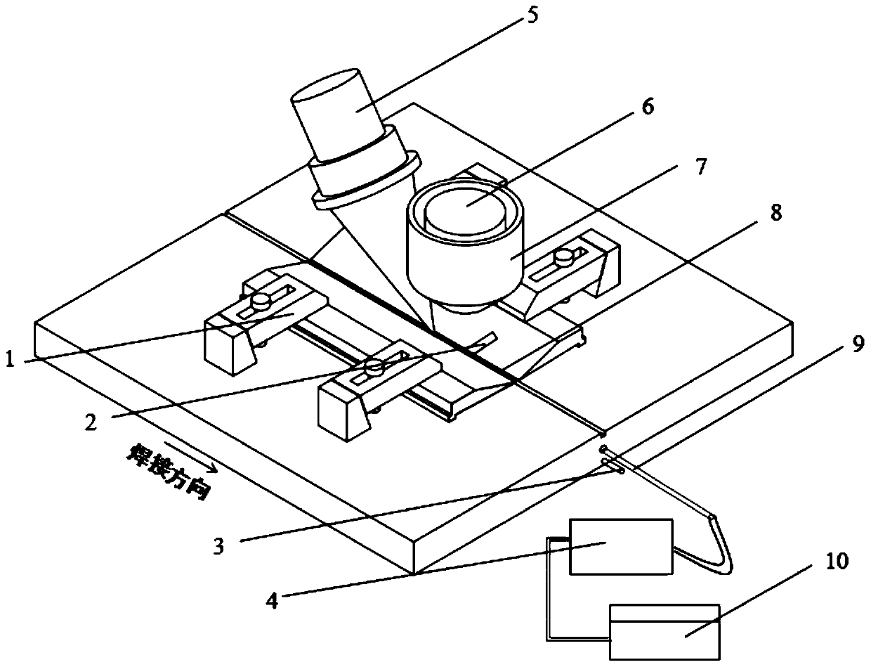
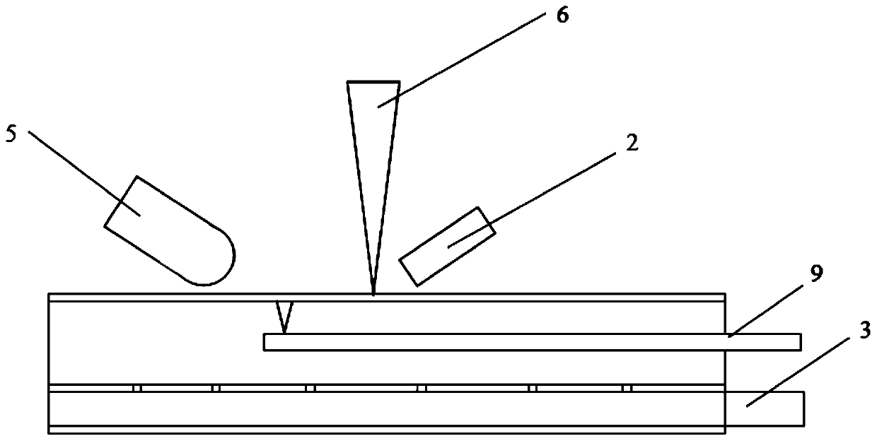
[0032] A. Place the Hastelloy C-276 plate with a thickness of 0.5mm on the fixture 1 and clamp it with copper clamps, and the distance between the clamps is 6mm. Place the jig 1 on the workbench, and fix the relative position of the jig 1 and the workbench.

[0033] B. Adjust the ultrasonic parameters. Adjust the ultrasonic head 5 so that it is 10mm directly behind the molten pool to ensure that the ultrasound can be transmitted into the molten pool. Adjust the angle of ultrasonic head 5 so that the axis of ultrasonic head 4 forms an angle of 30° with the horizontal. Adjust the position of the ultrasonic head 5 so that its top is 0.1mm lower than the surface of the workpiece; after the position of the ultrasonic head 5 is determined, fix it with the cantilever of the machine tool to ensure that the relative position of the two does not change during the welding process. Connect the ultrasonic vibrator to the ultrasonic generator, turn on the power of the ultrasonic generator...


PUM


Abstract

The invention belongs to the field of welding, and relates to a laser welding method combining ultrasonic welding with chilling. According to the method, cooling water is applied to the back surface of a welding seam with a certain distance behind a molten pool in the welding process, and ultrasonic vibration is applied to the front surface; the temperature and the flow of the cooling water are determined according to the welding mode used; and the ultrasonic application position, power and force are adjusted according to the mechanical properties of sample materials. According to the method,the welding residual stress can be effectively reduced, and air holes and cracks are reduced, so that the fatigue performance of the welding seam is improved, and meanwhile, transverse and longitudinal deformation of welding is reduced. Longitudinal residual stress and deformation can be effectively reduced through chilling and welding. The ultrasonic impact can counteract the transverse stress caused by chilling and welding, and further inhibit longitudinal stress, so that deformation is effectively reduced; and the acoustic streaming effect and cavitation effect of the ultrasonic can refinecrystal grains and reduce the air holes and cracks, so that the fatigue performance of the welding seam is improved.

Description

technical field [0001] The invention belongs to the field of welding and relates to a laser welding method combined with welding ultrasonic and chilling. Background technique [0002] Welding is a heating and cooling process with localized heating and cooling. When heated, the metal around the weld expands, producing compressive plastic deformation under the restraint of the fixture. When cooling, this part of the metal shrinks to produce tensile plastic deformation, elastic deformation and tensile stress. The stress that still exists after cooling to room temperature is the residual stress. When the clamp is released after welding, the residual stress is redistributed, and the workpiece is deformed under the action of the stress. It can be seen that the main cause of welding deformation is welding residual stress. [0003] The workpiece will produce residual stress after welding, which will cause welding deformation and reduce the fatigue performance of the weld. Theref...

Claims


Application Information

Patent Timeline
IPC IPC(8): B23K26/346B23K26/0622B23K26/70
CPCB23K26/0622B23K26/346B23K26/702
Inventor 马广义刘俊吴东江刘德华牛方勇
Owner DALIAN UNIV OF TECH
Why Eureka
Try Eureka