
Circuit breaker mechanism

A technology of circuit breaker mechanism and energy storage motor, which is applied to high-voltage air circuit breakers, circuits, electrical components, etc., can solve the problems of inconvenient assembly and maintenance, many parts, and inability to realize voltage interchange, and achieve simple and reliable parts and components. , The effect of compact internal structure, convenient assembly and maintenance

Active Publication Date: 2020-03-06
上海洪电电气有限公司
View PDF17 Cites 2 Cited by
  • Summary
  • Abstract
  • Description
  • Claims
  • Application Information

AI Technical Summary

Problems solved by technology

[0002] Most of the existing high-voltage vacuum circuit breakers use a spring operating mechanism, which can be divided into two installation methods: one is to install each component in a welded frame, and each transmission component is assembled and connected, but this method is time-consuming to assemble and overhaul. Extremely inconvenient, with many parts and high failure rate; the other adopts modular installation, that is, each part of the mechanism is made into an independent whole, and installed as a module in a welded frame. The traditional modular installation method has complex modules. , it is difficult to install, and the space is limited. The parts of the traditional mechanism module are small and easy to wear, and there are defects such as unstable mechanical characteristics and low life. Moreover, the traditional mechanism module has various installation methods, and it is impossible to realize the connection between voltage levels. Interchange, in order to solve the above problems, it is still necessary to design a circuit breaker mechanism

Method used


Image

  • Circuit breaker mechanism
  • Circuit breaker mechanism
  • Circuit breaker mechanism

Examples


Embodiment Construction

[0025] In order to make the technical means, creative features, goals and effects achieved by the present invention easy to understand, the present invention will be further described below in conjunction with specific embodiments.

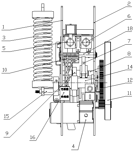
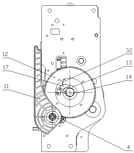
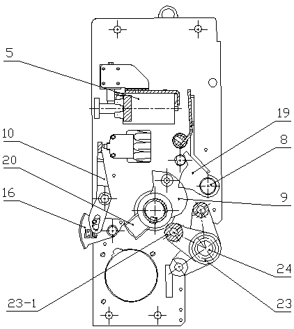
[0026] A circuit breaker mechanism according to the present invention comprises a left side plate (1), a right side plate (2), an energy storage spring (3), an energy storage motor (4), a closing electromagnet (5), an opening Electromagnet (6), opening pinch plate (7), closing branch shaft (8), closing cam (9), pressure plate (10), energy storage handle (11), energy storage gear (12), transmission wheel (13), energy storage shaft (14), rotating spring arm (15), energy storage indicator (16), transmission claw (17), opening half shaft (18), closing detent (19), clutch Cam (20), opening push plate (21), holding block (22), input holding crank arm (23), crank arm support shaft (24), upper air lock plate (25), lower air lock plate (26), chassis inter...


PUM


Abstract

The invention discloses a circuit breaker mechanism, and relates to the technical field of circuit breaker operating mechanisms. The circuit breaker mechanism is a modularly installed operating mechanism, and comprises a left side plate, a right side plate, an energy storage spring, an energy storage motor, a switching-on electromagnet, a switching-off electromagnet, a switching-off pinch plate, aswitching-on branch shaft, a switching-on cam, a pressing plate, an energy storage handle, an energy storage bull gear, a transmission wheel, an energy storage shaft, a rotating spring crank arm, anenergy storage indicator, a transmission claw, a switching-off half shaft, a switching-on latch, a clutch cam, a switching-off push plate, a hold block, an input hold crank arm, a crank arm supportingshaft, an upper air-closing interlocking plate, a lower air-closing interlocking plate, a chassis interlocking plate, an overhead screw, a clutch block, a gear side plate, a gear bearing, a leaf spring, a rotating sleeve, an energy storage motor or a manual energy storage output power source. Energy storage, closing and opening operation and an anti-misoperation interlocking function of the circuit breaker are achieved through mechanical cooperation of all parts of the mechanism, and the mechanism is simple and reliable in parts, convenient to maintain, stable in transmission, high in reliability and long in service life.

Description

technical field [0001] The present invention relates to the technical field of operating mechanism, in particular to an operating mechanism of a circuit breaker. Background technique [0002] Most of the existing high-voltage vacuum circuit breakers use a spring operating mechanism, which can be divided into two installation methods: one is to install each component in a welded frame, and each transmission component is assembled and connected, but this method is time-consuming to assemble and overhaul. Extremely inconvenient, with many parts and high failure rate; the other adopts modular installation, that is, each part of the mechanism is made into an independent whole, and installed as a module in a welded frame. The traditional modular installation method has complex modules. , it is difficult to install, and the space is limited. The parts of the traditional mechanism module are small and easy to wear, and there are defects such as unstable mechanical characteristics an...

Claims


Application Information

Patent Timeline
IPC IPC(8): H01H33/666
CPCH01H33/666
Inventor 梁作鹏
Owner 上海洪电电气有限公司
Learn More