Intelligent inertia energy saving system of pilotless vehicle and control method of intelligent inertia energy saving system

A technology of unmanned vehicles and energy-saving systems, which is applied in the field of intelligent inertial energy-saving systems of unmanned vehicles and its control, can solve the problems of low integration, low energy-saving efficiency, and inability to maximize the energy-saving efficiency of inertial energy-saving systems. The effect of optimizing material saving, increasing driving performance and safety performance, and facilitating utilization of inertial energy

Inactive Publication Date: 2020-03-10
浙江天尚元科技有限公司
View PDF5 Cites 3 Cited by
  • Summary
  • Abstract
  • Description
  • Claims
  • Application Information

AI Technical Summary

Problems solved by technology

The existing inertial energy-saving system fails to effectively utilize road environment information, resulting in low energy-saving efficiency
The braking energy recovery system is not integrated, the integration level is low, and the energy-saving efficiency is low; the energy-saving efficiency of the inertial energy-saving system cannot be maximized if it is not integrated with the unmanned driving platform

Method used


Image

  • Intelligent inertia energy saving system of pilotless vehicle and control method of intelligent inertia energy saving system

Examples


specific Embodiment 1

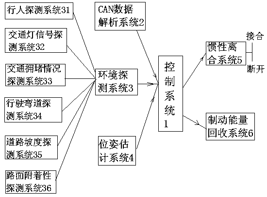
[0033] An intelligent inertial energy-saving system for unmanned vehicles, such as figure 1 As shown, it consists of control system 1, CAN data analysis system 2, environment detection system 3, pose estimation system 4, inertial clutch system 5 and braking energy recovery system 6, CAN data analysis system 2, environment detection system 3 and position The attitude estimation system 4 is respectively connected to the signal input end of the control system 1 , and the signal output end of the control system 1 is respectively connected to the inertial clutch system 5 and the braking energy recovery system 6 .

[0034] In this specific embodiment, the environment detection system 3 adopts binocular stereo camera image processing technology, and the environment detection system 3 includes a pedestrian detection system 31 for detecting whether there are pedestrians in front of the vehicle, and a traffic light signal detection system for detecting traffic light signals. System 32, ...

specific Embodiment 2

[0036] A control method for an intelligent inertia energy-saving system of an unmanned vehicle, the steps are as follows:

[0037] (1) First, analyze the CAN network data of the vehicle through the CAN data analysis system 2 (CANoe, Vector Company), and obtain the vehicle's accelerator pedal position data, brake pedal position data and steering wheel angle data;

[0038] (2) Through the environment detection system 3 (the binocular camera adopts ZED, Stereolabs, and the image calculation unit adopts TX2, NVIDIA), detect the traffic light signal, pedestrian information, traffic congestion information, road slope, driving curve angle and road surface in front of the vehicle Attachment data;

[0039] (3) Obtain the acceleration information and pitch angle information of the vehicle through the pose estimation system 4 (the binocular camera adopts ZED, Stereolabs, and the image calculation unit adopts TX2, NVIDIA);

[0040](4) Judging the traffic light conditions, and analyzing t...


PUM


Abstract

The invention discloses an intelligent inertia energy saving system of a pilotless vehicle and a control method of the intelligent inertia energy saving system. The intelligent inertia energy saving system is characterized by comprising a control system, a CAN data analysis system, an environment detection system, a pose estimating system, an inertia clutching system and a braking energy recovering system, wherein the CAN data analysis system, the environment detection system and the pose estimating system are respectively connected with a signal input end of the control system, and a signal output end of the control system is connected with the inertia clutching system and the braking energy recovering system respectively. The intelligent inertia energy saving system has the advantages ofutilization maximization of inertial energy, energy saving and emission reduction.

Description

technical field [0001] The invention relates to an intelligent inertial energy-saving system of an unmanned vehicle and a control method thereof. Background technique [0002] Despite strong policy support, pure electric vehicle technology has not been widely promoted due to the high cost of vehicle power batteries, low battery energy density, limited mileage, and charging piles are far from popular. "Technical Roadmap for Energy-Saving and New Energy Vehicles" pointed out that energy-saving vehicles should vigorously develop high-efficiency drive trains and reduce internal resistance and friction of drive trains. Inertial energy utilization technology fully meets this requirement. [0003] In recent years, inertial energy utilization technology has increasingly become one of the research and development hotspots. Japan's Toyota, Honda, Germany's Mercedes-Benz, BMW, Audi, etc. have successively added cars that use inertial energy randomly, but they can only use inertial en...

Claims


Application Information

Patent Timeline
Patent Type & Authority Applications(China)
IPC IPC(8): B60R16/023B60L7/10B60K17/02
CPCB60K17/02B60L7/10B60R16/0232
Inventor 史津竹马芳武代凯冯曙葛林鹤仲首任吴量单子桐郭荣辉吴官朴
Owner 浙江天尚元科技有限公司
Why Eureka
Try Eureka