Two-phase direct-current bias current vernier reluctance motor

A reluctance motor and DC bias technology, which is applied in the direction of AC motor control, magnetic circuit, electromechanical device, etc., can solve the problems of large torque pulsation, high vibration noise, weak magnetic field, etc., to improve strength, reduce switching devices, short end effect

Inactive Publication Date: 2020-03-13
XI AN JIAOTONG UNIV
View PDF9 Cites 1 Cited by
  • Summary
  • Abstract
  • Description
  • Claims
  • Application Information

AI Technical Summary

Problems solved by technology

The motor has the following disadvantages: the motor belongs to the category of reluctance motors in essence, and reluctance motors inevitably have the disadvantages of large torque ripple and high vibration noise; at the same time, because it uses direct current input, the excitation field is only Static magnetic field generated by a single direct current, weaker magnetic field results in lower torque

Method used


Image

  • Two-phase direct-current bias current vernier reluctance motor
  • Two-phase direct-current bias current vernier reluctance motor
  • Two-phase direct-current bias current vernier reluctance motor

Examples


Embodiment 1

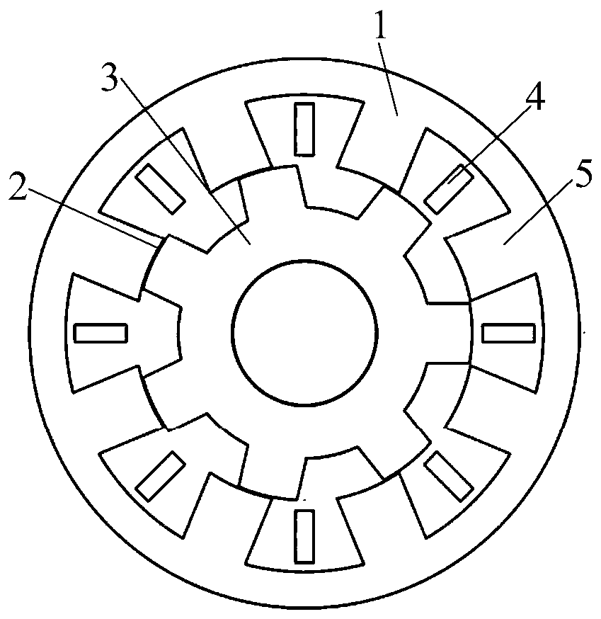
[0040] like figure 1 as shown, figure 1 It is the two-phase DC bias current vernier reluctance motor of embodiment 1, comprising a stator 1, an air gap 2, and a rotor 3, the stator 1 is sleeved on the periphery of the rotor 3, and an air gap 2 is arranged between the two, and the stator and the rotor are both A double-salient pole structure is adopted; the stator 1 includes a stator yoke, a stator end and a stator winding 4. The stator end is composed of a number of evenly distributed stator teeth 5, and the stator winding 4 is connected in a non-overlapping and centralized manner with fractional slots, alternately It is connected to half of the stator teeth 5; the air gap 2 has a great influence on the performance of the motor, and an appropriate air gap length is required. Here, 0.3mm is selected through optimization. In Embodiment 1, the stator has 8 slots, the rotor has 7 slots, the stator winding has 5 pairs of poles, and the number of DC excitation pole pairs is 2.

[...

Embodiment 2

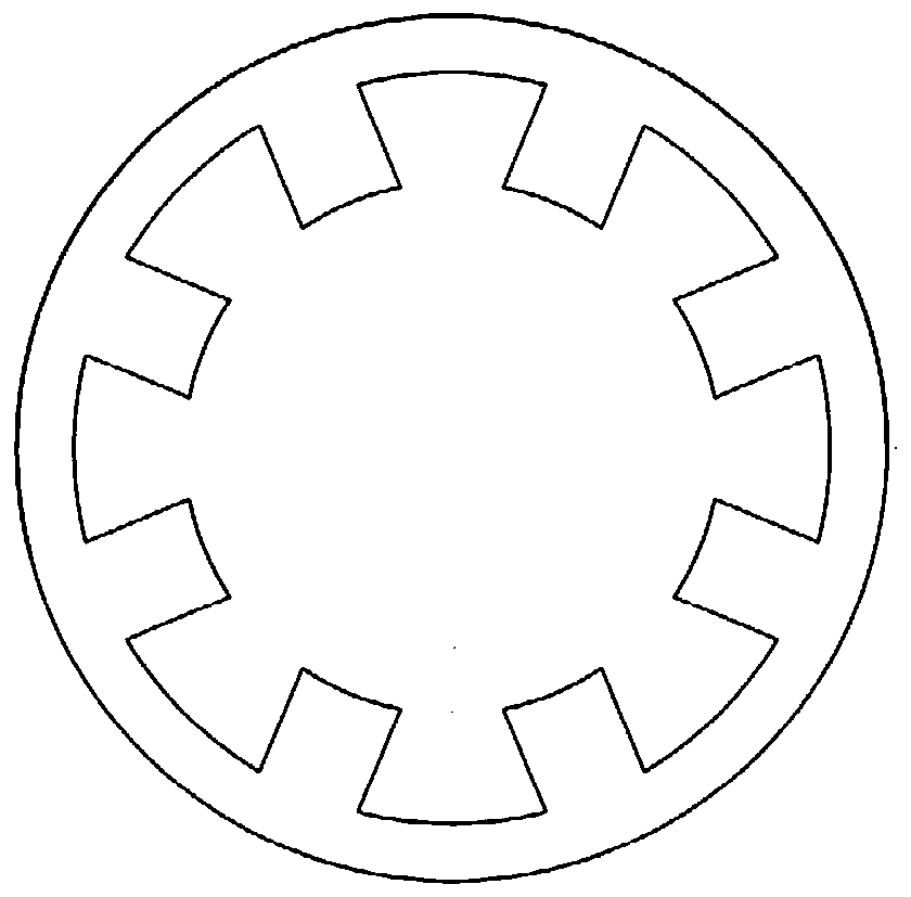
[0052] The motor of embodiment 2 is as Figure 5 As shown, the structure of the motor is basically the same, the only difference is that the slots and poles match and the direction of the direct current is different. like Figure 5 As shown, the motor also belongs to the two-phase DC bias current vernier reluctance motor, the stator has 8 slots, the rotor has 9 slots, the stator winding 4 has 5 pairs of poles, and the number of DC excitation pole pairs is 4. Structurally than figure 1 The embodiment adds 2 rotor slots; according to the counterclockwise or clockwise direction, the currents of the stator winding 4 are i A+ i B+ i A- and i B- , the purpose of doing this is to reconstruct the direction of the DC current so that it meets the slot-to-pole fit.

[0053] The use of this arrangement ensures on the one hand the number of pole pairs of the expected rotating fundamental magnetic field generated by the AC current, and on the other hand ensures the number of pole pair...


PUM


Abstract

The invention discloses a two-phase direct-current bias current vernier reluctance motor, and belongs to the technical field of motors. The motor comprises a stator and a rotor. The stator and the rotor both adopt double-salient-pole structures, the stator sleeves the periphery of the rotor, and an air gap is formed between the stator and the rotor; the stator comprises a stator yoke part, a stator end part and stator windings; a plurality of stator teeth are uniformly distributed at the stator end part; the stator windings are connected in a fractional slot non-overlapping concentration modeand are alternately connected to half of the stator teeth; the stator windings are powered by two-phase composite current, the two-phase composite current is formed by superposing a direct current and an alternating current, and the phase difference of the introduced alternating current is 90 degrees. The composite current of the direct current and the alternating current is introduced into the stator winding, and the performance of the existing two-phase motor is improved from the working principle through the application of the magnetic field modulation principle. By applying a magnetic field modulation principle, the intensity of an excitation magnetic field is improved, and the torque density and high efficiency can also be ensured under the condition of no permanent magnet.

Description

technical field [0001] The invention belongs to the technical field of motors, in particular to a two-phase DC bias current vernier reluctance motor. Background technique [0002] At present, permanent magnet motors are widely used in electric vehicles, numerical control machine tools, wind power generation, servo drives and other occasions due to their significant advantages in torque density, efficiency and power factor. Permanent magnet motors have become a hot spot for researchers. Permanent magnet motors with various topological structures and superior performance have been proposed and studied in depth, especially three-phase permanent magnet motors have been widely used in practical applications. However, the permanent magnet motor has the problem that the magnetization cannot be demagnetized due to loss of magnetism and short circuit fault. In addition, permanent magnet materials are expensive, and the application of permanent magnet motors in cost-sensitive applica...

Claims


Application Information

Patent Timeline
Patent Type & Authority Applications(China)
IPC IPC(8): H02K1/24H02K1/14H02K3/18H02K3/28H02P25/08H02P25/092H02P27/00
CPCH02K1/146H02K1/24H02K3/18H02K3/28H02P25/08H02P25/092H02P27/00
Inventor 贾少锋闫宽宽梁得亮诸自强刘进军
Owner XI AN JIAOTONG UNIV
Why Eureka
Try Eureka