Wavelength conversion device and light source system
A technology of wavelength conversion device and wavelength conversion layer, which is applied in projection devices, lighting devices, components of lighting devices, etc., can solve the problems of increasing the thermal resistance of the reflective layer and reducing the heat dissipation performance, so as to improve the light efficiency and collection efficiency Consistent, the effect of improving light extraction efficiency
- Summary
- Abstract
- Description
- Claims
- Application Information
AI Technical Summary
Problems solved by technology
Method used
Image
Examples
Embodiment 1
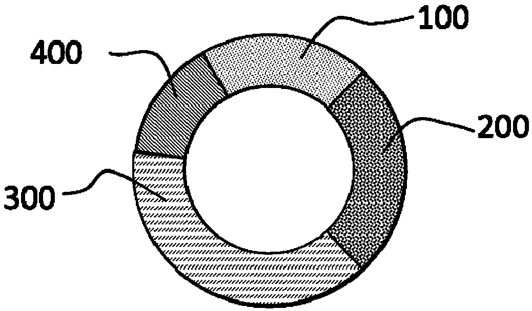
[0047] The present invention provides a wavelength conversion device for emitting received light under the irradiation of excitation light, which includes a wavelength conversion part and a non-wavelength conversion part.
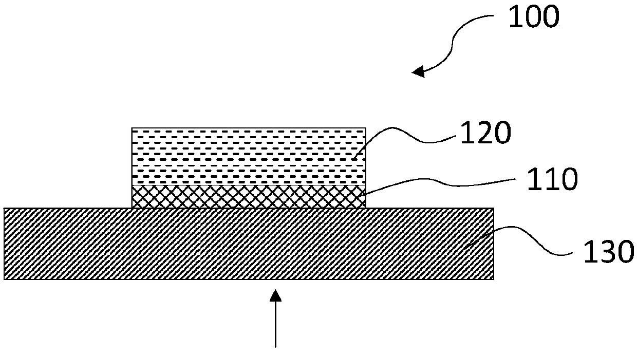
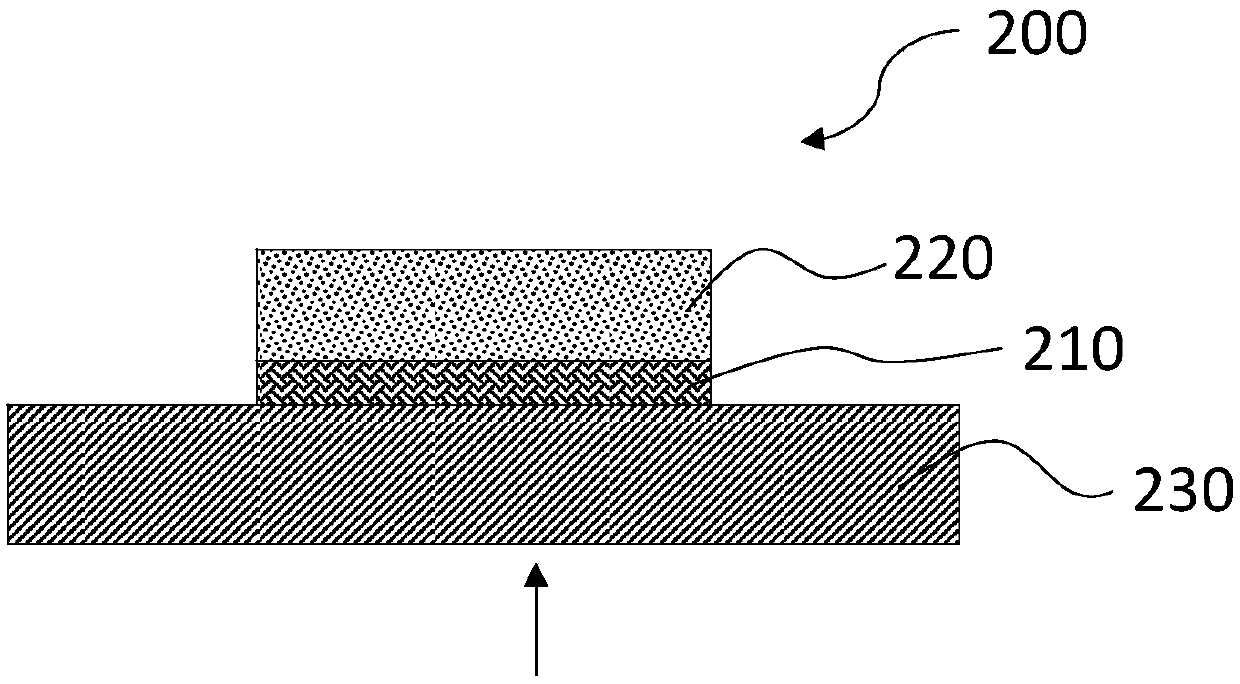
[0048] The wavelength conversion part includes a plurality of wavelength conversion modules, and each wavelength conversion module is fan-shaped. Each wavelength conversion module includes a transparent heat-conducting substrate, a wavelength conversion layer, and a reflection layer arranged in sequence along the incident direction of the excitation light. The color of the wavelength conversion layer can be Red, yellow, green, orange or cyan, etc. Specifically, when the wavelength conversion part includes a first wavelength conversion module and a second wavelength conversion module, the first wavelength conversion module includes a first transparent heat-conducting substrate, a first wavelength conversion layer, and a first The reflective layer, the second...
Embodiment 2
[0087] Compared with the first embodiment, this embodiment differs in that the wavelength conversion layer of the third wavelength conversion module is made of yellow fluorescent ceramics. Due to the current YAG: Ce 3+ The preparation process of yellow fluorescent ceramics is relatively mature, and its luminous efficiency has surpassed the combination of inorganic adhesives and yellow fluorescent powder, and has great advantages in heat resistance, thermal conductivity and reliability.
[0088] In this embodiment, the manufacturing steps of the improved third wavelength conversion module are as follows:
[0089] printing a third reflective slurry layer on the non-polished surface of the yellow fluorescent ceramics polished on one side, and drying the third reflective slurry layer;
[0090] On one side of the third transparent heat-conducting substrate, a yellow-light color-correcting coating layer is deposited by vacuum evaporation or magnetron sputtering. The function of th...
Embodiment 3
[0094] Compared with the second embodiment, this embodiment differs in the structure of the first wavelength conversion module.
[0095] Figure 9 It is a cross-sectional view of the first wavelength conversion module in Embodiment 3 of the present invention. Due to the poor heat resistance of the red phosphor, in order to improve the heat resistance of the first wavelength conversion module, such as Figure 9 As shown, in this embodiment, a fluorescent ceramic layer (yellow fluorescent ceramic 310') is also provided between the first wavelength conversion layer 110 of the first wavelength conversion module and the first transparent heat-conducting substrate 130, that is, the first wavelength conversion layer in this embodiment. A wavelength conversion module includes a first transparent heat-conducting substrate 130 , a yellow fluorescent ceramic 310 ′, a first wavelength conversion layer 110 and a first reflection layer 120 sequentially arranged along the incident direction...
PUM
| Property | Measurement | Unit |
|---|---|---|
| Particle size | aaaaa | aaaaa |
| Particle size | aaaaa | aaaaa |
| Particle size | aaaaa | aaaaa |
Abstract
Description
Claims
Application Information
 - R&D
- Intellectual Property
- Life Sciences
- Materials
- Tech Scout
- Unparalleled Data Quality
- Higher Quality Content
- 60% Fewer Hallucinations
Browse by: Latest US Patents, China's latest patents, Technical Efficacy Thesaurus, Application Domain, Technology Topic, Popular Technical Reports.
© 2025 PatSnap. All rights reserved.Legal|Privacy policy|Modern Slavery Act Transparency Statement|Sitemap|About US| Contact US: help@patsnap.com


