Barnacle removing device capable of generating power by using ocean energy

A barnacle and marine technology, applied in the field of barnacle removal devices, can solve the problems of shortened service life, rapid consumption, and long formation process, and achieve the effects of reducing maintenance costs, reducing workload, and reducing growth

Active Publication Date: 2020-03-24
山东辰升科技有限公司
10 Cites 2 Cited by

AI-Extracted Technical Summary

Problems solved by technology

[0002] Coal, oil, and natural gas are non-renewable. Their formation process is very long, but their consumption is very fast. Therefore, people have developed new energy sources, which mainly include solar energy, ocean energy, wind energy, and geothermal energy. Among them, in In the process of using ocean energy to generate electricity, the appearance of certain marine organisms has brought troubles to people: such as barnacles, which are marine crustaceans. Due to their special morphological structure, life history and population ecology, they have become the most One of the main marine fouling organisms, whose adults can neither swim nor crawl, and mostly live in the intertidal zone, attaching to and inhabiting on fixed or floating hard objects in seawater. Among them, the device that uses ocean currents to generate electricity in the ocean nature can't avoid
[0003] Barnacle...

Method used

By ball column 11, pressing column 12 and compression spring 13, can single a small amount of alkaline aqueous solution in housing 1 be extruded from housing 1, if there is unnecessary alkaline aqueous solution, there is no If it is absorbed into the water storage shell 9 by the water-absorbing block 10, it can be stored in the ball column 11, and when the next turbine blade 8 rotates, it can continue to absorb, or spread with the ocean current, so that the solute in the solution, that is, slaked lime, is attached to the Reduces barnacle growth on power plants.
Through the cooperative use of turbine blade 8, water storage shell 9, water-absorbing block 10, ball column 11 and pressing column 12, the alkaline solution in the housing 1 can ...

Abstract

The invention relates to the technical field of new resources, and discloses a barnacle removing device capable of generating power by using ocean energy. The device comprises a casing, wherein a connecting rod is fixedly installed on the lower surface of the casing, fixing brackets are fixedly installed on the lower end of the connecting rod, and baffles are fixedly installed on the upper surfaceof the casing; fixing columns are fixedly installed on the upper surface of the casing, and rotating shafts are fixedly installed on the fixing columns. Through cooperative use of a ball column, a pressing column and a pressure spring, a small amount of an alkaline aqueous solution in the casing can be squeezed out of the casing every time, an excessive part, which is not absorbed into a water storage shell by a water absorption block, of the alkaline aqueous solution can be stored in the ball column, and when a next turbine blade rotates to the ball column, continuous absorption is achieved,or diffusion with a ocean current is achieved, so that a slaked lime solute in the solution is adhered to a power generation device, and the growth of barnacles is reduced.

Application Domain

Hydro energy generationReaction engines +3

Technology Topic

Aqueous solutionTurbine blade +8

Image

  • Barnacle removing device capable of generating power by using ocean energy
  • Barnacle removing device capable of generating power by using ocean energy
  • Barnacle removing device capable of generating power by using ocean energy

Examples

  • Experimental program(1)

Example Embodiment

[0020] The technical solutions in the embodiments of the present invention will be clearly and completely described below in conjunction with the accompanying drawings in the embodiments of the present invention. Obviously, the described embodiments are only a part of the embodiments of the present invention, rather than all the embodiments. Based on the embodiments of the present invention, all other embodiments obtained by those of ordinary skill in the art without creative work shall fall within the protection scope of the present invention.
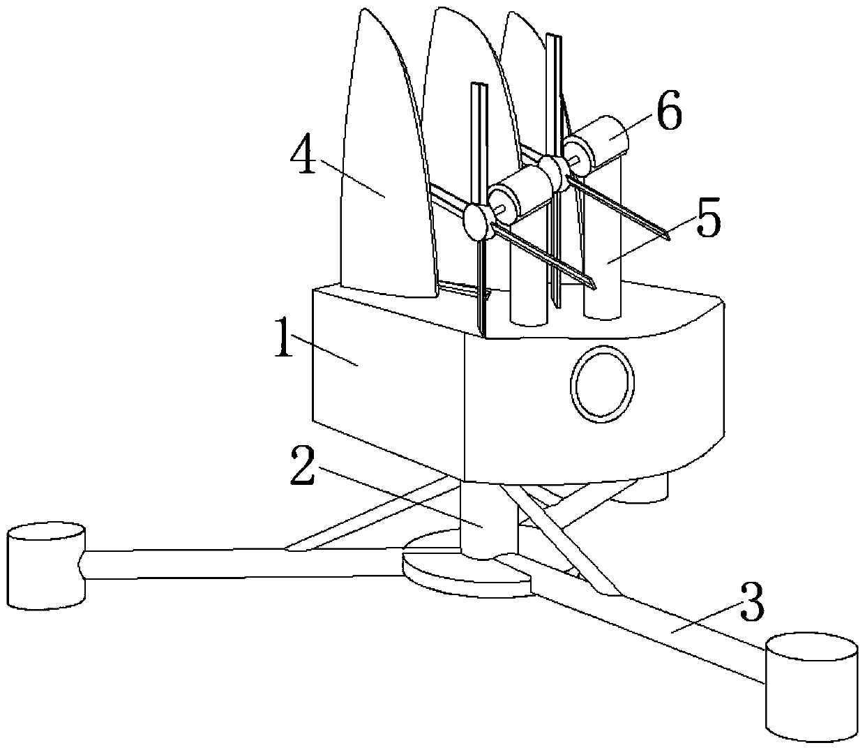
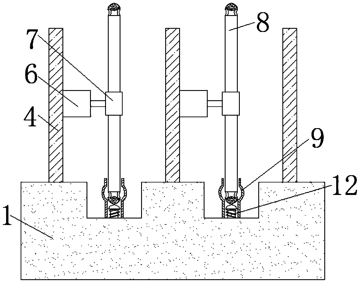
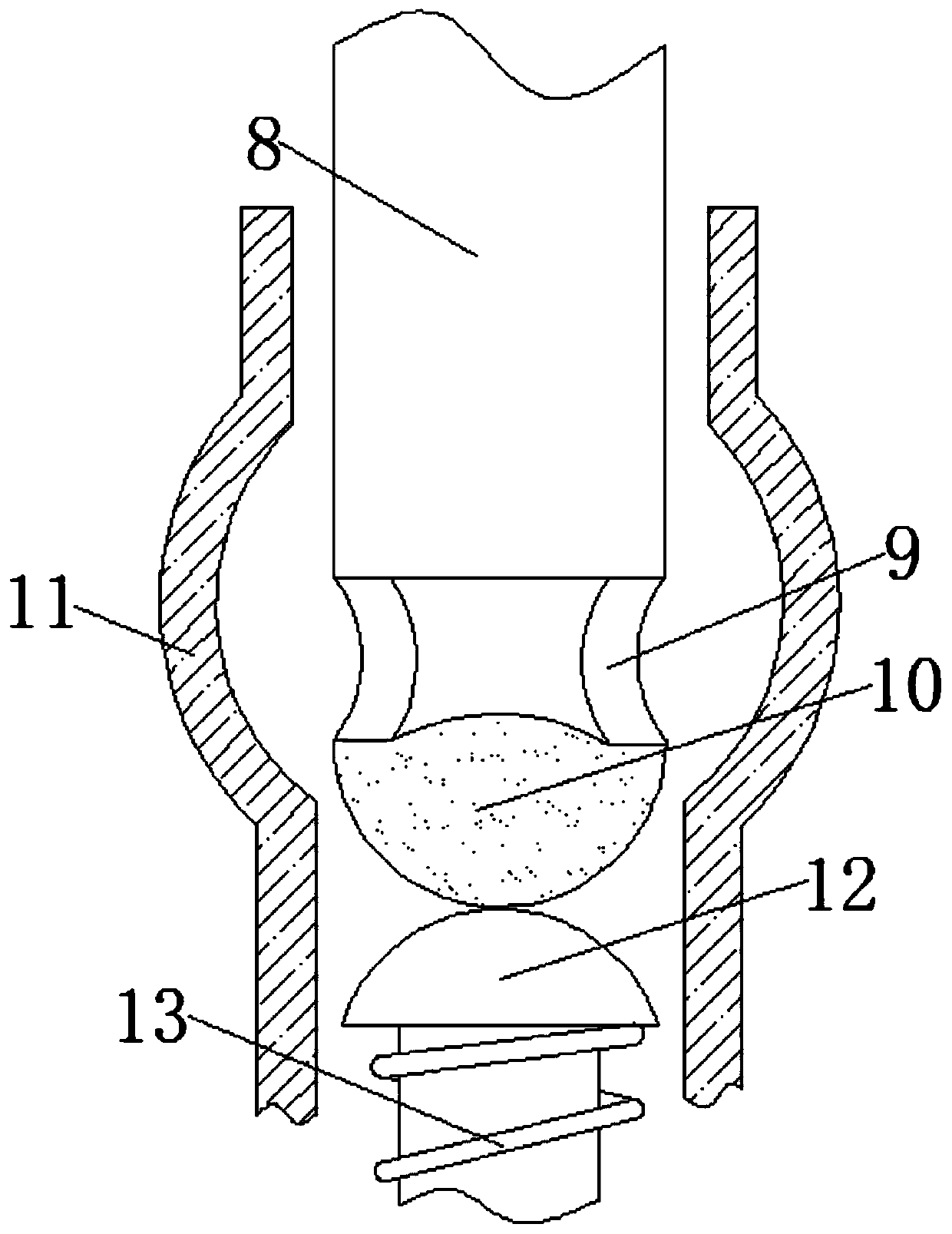
[0021] See Figure 1-3 , A barnacle removal device that utilizes ocean energy to generate electricity, comprising: a shell 1, an alkaline solution with a PH value greater than 8.5 is arranged inside the shell 1, because it is understood that the suitable seawater pH for barnacle growth is 7.5 to 8.5 The high or low physical and chemical factors of these seawater are not conducive to the growth and reproduction of barnacles. As long as the PH value on the turbine blade 8 is greater than 8.5, it will not be conducive to the growth of barnacles, thereby reducing the adhesion of barnacles and protecting the turbine. Ye 8, here can be replaced with lime water, lime water is calcium oxide solution, people generally use to neutralize the acidity and alkalinity of the land, pollution is less.
[0022] Such as figure 1 Shown: a connecting rod 2 is fixedly installed on the lower surface of the housing 1, a fixing frame 3 is fixedly installed on the lower end of the connecting rod 2, a baffle 4 is fixedly installed on the upper surface of the housing 1, and the baffle 4 is located on the upper part of the housing 1. There are three equal intervals on the surface, and the turbine blades 8 are located between the adjacent baffles 4, and the fixed column 5 is located directly in front of the baffle 4. The upper surface of the housing 1 is fixedly installed with a fixed column 5, A rotating shaft 6 is fixedly installed on the upper part, a connecting block 7 is fixedly installed on the front of the rotating shaft 6, and a turbine blade 8 is fixedly installed on the outer side of the connecting block 7. The connecting block 7 and the turbine blade 8 are fixedly installed in a screw connection, mainly for easy replacement A single turbine blade 8, the lower end of the turbine blade 8, the water storage shell 9 and the water absorption block 10 are located inside the ball column 10, mainly located when the turbine blade 8 rotates, the column 12 can be pressed downward to help the shell 1 The alkaline solution inside is squeezed out, the side of the turbine blade 8 is provided with a groove, and a capillary tube is fixedly installed inside the groove. The lower end of the capillary tube is inserted into the water storage shell 9 to help the water storage shell 9 Alkaline water penetrates into the turbine blade 8 through capillary phenomenon to reduce the adhesion of barnacles. The end of the turbine blade 8 away from the connecting block 7 is fixedly installed with a water storage shell 9.
[0023] Such as figure 2 As shown: a water absorption block 10 is fixedly installed at one end of the water storage shell 9 away from the turbine blade 8. The water absorption block 10 is made of a hard material, and the water storage shell 9 is filled with sponge.
[0024] Such as image 3 Shown: the lower end of the water absorption block 10 is overlapped with a pressing column 12, the lower end of the pressing column 12 is movably installed with the lower end of the groove of the housing 1, and the west section of the pressure spring 13 is overlapped with the groove of the housing 1, pressing A pressure spring 13 is sleeved on the outer surface of the column 12, a ball column 11 is fixedly installed in the groove of the housing 1, and a groove is opened on the left side of the housing 1 and located between the two baffles 4 adjacent to each other. The column 11 is located inside the groove.
[0025] Through the use of the ball column 11, the pressing column 12 and the pressure spring 13, the alkaline aqueous solution in the housing 1 can be squeezed out of the housing 1 in a small amount at a time. If there is excess alkaline aqueous solution that is not absorbed by the water block 10 If it is absorbed into the water storage shell 9, it can be stored in the ball column 11. When the next turbine blade 8 rotates, it can continue to absorb or diffuse with the ocean current, so that the solute in the solution, namely slaked lime, is attached to the power generation device. , To reduce the growth of barnacles.
[0026] Wherein, an acid-base meter is fixedly installed on the outer surface of the water-absorbing block 10, and the water-absorbing block 10 can absorb it only when the side of the acid-base meter shows that the solution is alkaline.
[0027] Among them, the pressing column 12 is pressed to produce water.
[0028] Among them, the baffle 4 is mainly to block part of the ocean current, so as to prevent the water storage shell 9 and the water absorption block 10 on the turbine blade 8 from being washed away by the ocean current as soon as they absorb some alkaline solution, giving the capillary on the turbine blade 8 a little absorption and diffusion The time of the alkaline solution.
[0029] Through the combined use of the turbine blade 8, the water storage shell 9, the water absorption block 10, the ball column 11 and the pressing column 12, the alkaline solution in the shell 1 can be squeezed out, and enter the water storage shell 9 through the water absorption column 10. Then through the capillary phenomenon, the alkaline solution is diffused on the turbine blade 8 to make it unsuitable for the growth environment of the barnacles, thereby reducing the attachment or even non-attachment of the barnacles to the turbine blades 8, which can ensure ocean energy generation The turbine blades 8 of the device are not attached to the barnacles, which protects the turbine blades 8 from being corroded by the acidic substances produced by the barnacles, prolongs the life of the turbine blades 8, and does not require staff to clean the power generation device regularly, reducing This reduces the workload of the staff and reduces maintenance costs.
[0030] In use, when the ocean current in the ocean flows from front to back, it drives the counterclockwise turbine blade 8 to rotate and generate electricity. When the turbine blade 8 rotates to generate electricity, the lower end of the turbine blade 8 rotates into the ball column 11 and passes through the water absorption block. 10 Press down the pressing column 12, and after pressing the pressing column 12 down, a little water will be drawn from the housing 1 for absorption by the water absorption block 10, and then the sponge in the water storage shell 9 will absorb the water absorption block 10 The pressed alkaline water is then diffused onto the turbine blade 8 through a capillary tube. After the turbine blade 8 rotates one round, the alkaline solution on it is almost washed away by the ocean current, and the pressing column 12 is pressed again.
[0031] Although the embodiments of the present invention have been shown and described, those of ordinary skill in the art can understand that various changes, modifications, and substitutions can be made to these embodiments without departing from the principle and spirit of the present invention. And variations, the scope of the present invention is defined by the appended claims and their equivalents.

PUM

no PUM

Description & Claims & Application Information

We can also present the details of the Description, Claims and Application information to help users get a comprehensive understanding of the technical details of the patent, such as background art, summary of invention, brief description of drawings, description of embodiments, and other original content. On the other hand, users can also determine the specific scope of protection of the technology through the list of claims; as well as understand the changes in the life cycle of the technology with the presentation of the patent timeline. Login to view more.

Similar technology patents

Composite ultrasonic vibration stirring ball-milling equipment and use method

ActiveCN112742548Areduce adhesionimprove distribution
Owner:济南重工集团有限公司

Protection device for hydraulic hinge steering rod of road roller

Owner:莆田市荔城区任西贸易有限公司

MEMS microphone chip

Owner:RUISHENG NEW ENERGY DEV CHANGZHOU +1

Ultrasonic suspension rotary micro-channel plate corrosion method

ActiveCN111863582Areduce adhesionImprove shape
Owner:NORTH NIGHT VISION TECH

Easy-to-wash ceramic soup cooking pot and preparation process thereof

InactiveCN106518001Areduce adhesionNot easy to dust and scale
Owner:ANHUI QINGHUAFANG FINE BONE PORCELAIN

Classification and recommendation of technical efficacy words

  • extend your life
  • reduce adhesion

Light-emitting element

ActiveCN103081155AImprove quantum efficiencyextend your life
Owner:SEMICON ENERGY LAB CO LTD

Method, system and device for controlling vehicle power device and storage medium

ActiveCN108394401AAvoid violent dynamic load changesextend your life
Owner:TSINGHUA UNIV

Packaging method for white light illuminating diode

InactiveCN101068034AReduce light decay rateextend your life
Owner:NINGBO ANDY OPTOELECTRONIC CO LTD

Metal drawing oil

InactiveCN103031189Areduce heatextend your life
Owner:LOCKS LUBE SHANGHAI
Why Eureka
Try Eureka