A kind of plastic film and processing system and processing technology
A plastic film and processing system technology, which is applied in the field of plastic film processing, can solve the problems that the film cannot be rolled and the width of the film cannot be adjusted, and achieves the effect of uniform composition
- Summary
- Abstract
- Description
- Claims
- Application Information
AI Technical Summary
Problems solved by technology
Method used
Image
Examples
specific Embodiment approach 1
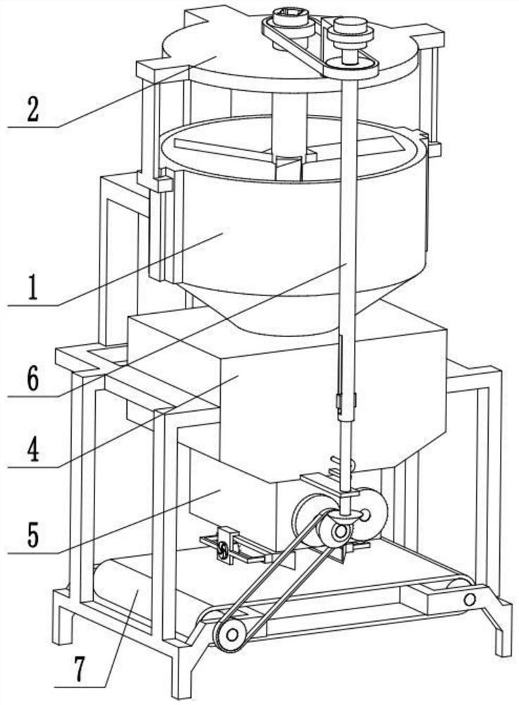
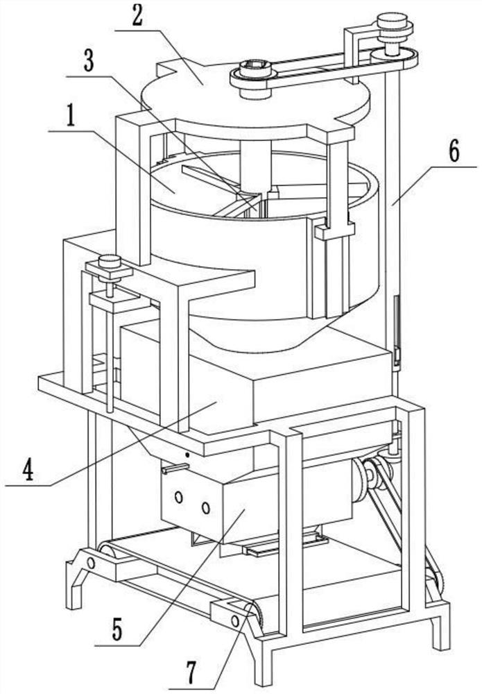
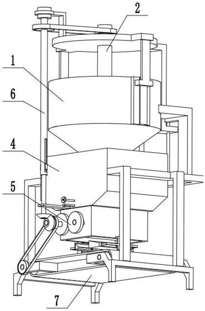
[0039] Combine below Figure 1-14 Describe this embodiment, a plastic film processing system, including a crushing cylinder 1, a particle crushing mechanism 2, a stirring body 3, a film discharge mechanism 4, a film rolling mechanism 5, a telescopic transmission mechanism 6 and a conveying frame 7, the The particle crushing mechanism 2 is set on the crushing cylinder 1, and the crushing cylinder 1 communicates with one end of the film discharge mechanism 4. Both the film discharge mechanism 4 and the particle crushing mechanism 2 are set on the conveying frame 7, and the film rolling mechanism 5 is set on the film On the other end of the discharge mechanism 4, the telescopic transmission mechanism 6 is located on the particle crushing mechanism 2 and the film discharge mechanism 4, and the two ends of the telescopic transmission mechanism 6 are respectively connected with the particle crushing mechanism 2 and the film rolling mechanism 5. 5 is in transmission connection with t...
specific Embodiment approach 2
[0040] Combine below Figure 1-14 To illustrate this embodiment, the crushing cylinder 1 is provided with a trapezoidal slide bar 1-1, an inverted conical heating chamber 1-2, a particle filter plate 1-3, a raw material filter plate 1-4 and an electric heating wire 1-5 The two ends of the crushing cylinder 1 are respectively provided with a trapezoidal slide bar 1-1, the lower end of the crushing cylinder 1 is fixedly connected to the particle filter plate 1-3, and the particle filter plate 1-3 is evenly distributed with a plurality of filter holes, and the crushing cylinder 1 The lower end of the upper end is fixedly connected and communicated with the conical heating chamber 1-2, and the lower end of the inverted conical heating chamber 1-2 is fixedly connected with the raw material filter plate 1-4, and the raw material filter plate 1-4 is evenly distributed with a plurality of filtrate holes, and the inverted cone The inner wall of the shaped heating chamber 1-2 is provide...
specific Embodiment approach 3
[0041] Combine below Figure 1-14 To illustrate this embodiment, the particle crushing mechanism 2 includes a fixed frame 2-1, a first motor 2-2, a lead screw 2-3, a Z-shaped telescopic plate 2-4, a top cover 2-5, and a vertical plate 2- 6. The slider 2-7, the first hollow shaft 2-8, the crushing knife 2-9 and the first pulley 2-10; the fixed frame 2-1 is set on the conveying frame 7, and the first motor 2-2 passes through The motor frame is fixedly connected to the fixed frame 2-1, the output shaft of the first motor 2-2 is connected to the lead screw 2-3 through a coupling, and one end of the Z-shaped telescopic plate 2-4 is connected to the lead screw 2-4 through thread fit. 3, the Z-shaped telescopic plate 2-4 is slidingly connected to the fixed frame 2-1, and the other end of the Z-shaped telescopic plate 2-4 is fixedly connected to the top cover 2-5, and the top cover 2-5 is coaxial with the crushing cylinder 1 , the two ends of the top cover 2-5 are respectively fixedl...
PUM
 Abstract
Description
Claims
Application Information
 - R&D
- Intellectual Property
- Life Sciences
- Materials
- Tech Scout
- Unparalleled Data Quality
- Higher Quality Content
- 60% Fewer Hallucinations
Browse by: Latest US Patents, China's latest patents, Technical Efficacy Thesaurus, Application Domain, Technology Topic, Popular Technical Reports.
© 2025 PatSnap. All rights reserved.Legal|Privacy policy|Modern Slavery Act Transparency Statement|Sitemap|About US| Contact US: help@patsnap.com


