Remote control system for intelligently monitoring material deposition in pipeline in pneumatic conveying
A pneumatic conveying and intelligent monitoring technology, applied in the direction of conveying bulk materials, conveyors, transportation and packaging, etc., can solve the problems of increased measurement data error, complex deposition detection terminal, and inability to apply large output, etc., to achieve long output distance, Easy installation, convenient remote monitoring effect
- Summary
- Abstract
- Description
- Claims
- Application Information
AI Technical Summary
Problems solved by technology
Method used
Image

Examples
Embodiment 1
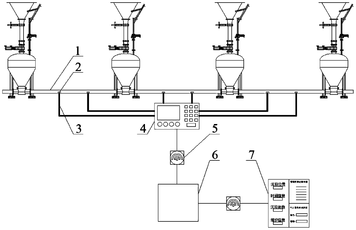
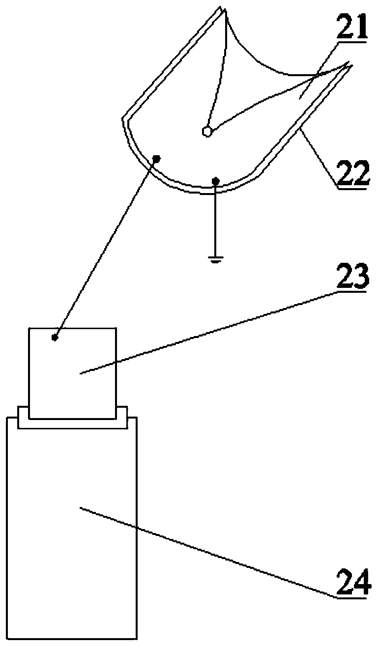
[0042] In this embodiment, a remote control system for intelligent monitoring of material deposition in pipelines during pneumatic conveying (see Figure 1-4 ), including: double casing 1, deposition detection terminal 2, wired communication module 3, main controller 4, wireless communication module 5, cloud server 6, mobile phone client 7. The deposition detection terminal 2 is laid on the lower pipe wall at the bottom of the double casing 1, and the distance between two adjacent deposition detection terminals 2 is set to 2m. The deposition detection terminal 2 is connected to the main controller 4 through a wired communication module 3, the wired communication module 3 adopts a 485 bus, the main controller 4 and the cloud server 6 are connected through a wireless communication module 5, the wireless communication module adopts a Lora wireless module, and the cloud server 6 Also connect with mobile phone client 7 by wireless communication module 5.
[0043] The main controll...
Embodiment 2
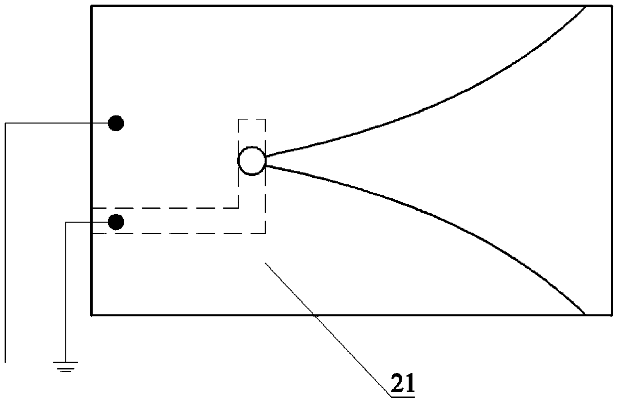
[0055] In this embodiment, the position and connection relationship of each part in a remote control system for intelligent monitoring of material deposition in pipelines in pneumatic conveying is the same as that in Embodiment 1 (see figure 1 ). The difference is that the contour shape of the capacitive antenna 21 is changed to a circular contour structure (see Figure 7 ), and the insulating sheet 22 is the same size as the capacitive antenna 21, with a diameter of 20 cm, which can be bent freely and connected to the bottom of the pipeline by welding. The capacitive antenna 21 can satisfy S 11 A requirement that is directly related to the thickness of the deposited layer. In this embodiment, the distance between two adjacent deposition detection terminals 2 is set to 3m. The rounded profile allows for easy installation and an easier fit to the inner wall of the pipe.
[0056] The system in this embodiment can realize the wireless monitoring of the deposition amount at mu...
Embodiment 3
[0058] The structure of this embodiment is the same as that of Embodiment 1, except that the structure of the deposition detection terminal in this embodiment is: the insulating sheet 22 and the capacitive antenna 21 have a width of 1 cm and a length of 2 cm, and are placed in a straight pipe section with a pipe diameter of 2 cm. . Adopting the structure in this embodiment, the material (solid phase) accounted for the overall fraction is 0.12 to carry out the pneumatic conveying simulation experiment, used to fit the relationship between the capacitance and the deposition quality,
[0059] Figure 8 Shown is the relationship between the capacitance of the measured capacitive antenna 21 and the deposition quality of the material particles. It can be seen that the capacitance value increases with the increase of the deposition quality of the material particles, and the relationship between the capacitance and the deposition quality is obtained through experimental fitting. y=23...
PUM
| Property | Measurement | Unit |
|---|---|---|
| Length | aaaaa | aaaaa |
| Width | aaaaa | aaaaa |
| Thickness | aaaaa | aaaaa |
Abstract
Description
Claims
Application Information